
JH-W7 Foot Switch
Model JH-W7
Compact PC foot switch with microswitch or reed-switch options and an optional mounting plate.
- Series / ModelJH-W7
- HousingEngineering plastic PC
- Microswitch Rating8A at 250VAC; F/H: 3A at 250VAC
- Contact Forms1a / 1c, depending on model
- ProtectionStandard IP54; F/H options IP67
Description
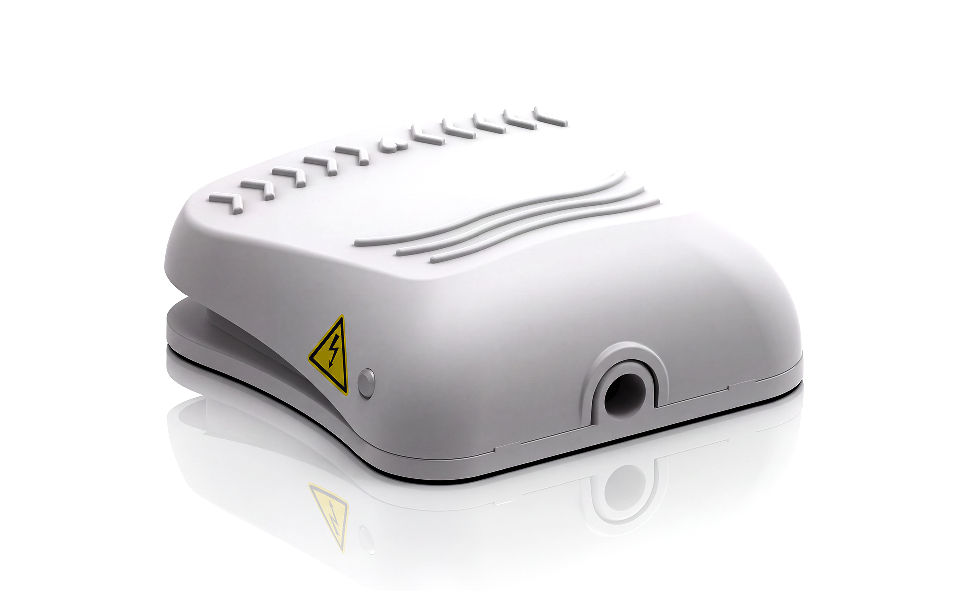
The JH-W7 is a compact foot switch with an engineering-plastic PC pedal and base. It is available with a standard microswitch, waterproof microswitch or reed switch for low-current signal control.
- Standard V15F-01C microswitch and optional F: V05F-14 / H: V05F-04G waterproof microswitches.
- Standard IP54 version; F and H waterproof options are specified as IP67.
- Optional SUS304 stainless-steel mounting plate.
- Grey (C) and Tiffany blue (T); other colours and connector configurations by request.
Specifications
| Series / Model | JH-W7 |
|---|---|
| Housing | Engineering plastic PC |
| Microswitch Rating | 8A at 250VAC; F/H: 3A at 250VAC |
| Contact Forms | 1a / 1c, depending on model |
| Protection | Standard IP54; F/H options IP67 |
| Mounting Plate | Optional SUS304 stainless steel |
| Operating Force | 14.5N |
| Insulation Resistance | ≥100MΩ at 500VDC |
| Contact Resistance | Microswitch: <25mΩ initially; reed: <150mΩ initially |
| Dielectric Test, Microswitch | 1000VAC between live parts; 2500VAC to non-live parts, 1 minute |
| Max. Switching Voltage, Micro | 250VAC / 125VDC |
| Max. Switching Current, Micro | 8A AC / 2A DC; model-specific limits apply |
| Max. Switching Voltage, Reed | 180VDC / 130VAC |
| Max. Switching Current, Reed | 0.5A; maximum switching power 10W |
| Mechanical Life | ≥1,000,000 operations |
| Electrical Life, Microswitch | ≥100,000 operations |
| Electrical Life, Reed | 1×10⁶ at 24V/250mA; 1×10⁷ at 5V/10mA |
| Ambient Temperature | -25°C to +70°C, no condensation or icing |
| Catalogue Standards | IEC/EN60947-5-1; GB14048.5-2017 |
| Protection Test Reference | IEC/EN60529 |
Catalogue model variants
| Model (* = colour) | Version | Contacts | Switch rating / limits | Weight |
|---|---|---|---|---|
| JH-W7* | Basic; V15F-01C microswitch | 1a | 8A, 250VAC | 0.134kg |
| JH-W7*-A | Audio connector option | 1a or 1c | 8A, 250VAC | 0.186kg |
| JH-W7*-D | DB9 serial connector option | 1a or 1c | 8A, 250VAC | Specified separately |
| JH-W7*-U | USB connector option | 1a | 8A, 250VAC | Specified separately |
| JH-W7*-P | Aviation connector option | 1a or 1c | 8A, 250VAC | Specified separately |
| JH-W7*-F | Waterproof microswitch | 1c | 3A, 250VAC | 0.216kg |
| JH-W7*-H | Miniature waterproof microswitch | 1a | 3A, 250VAC | 0.129kg |
| JH-W7*-M | Reed switch, signal control | 1a | 0.5A max.; 10W max. | 0.125kg |
The basic cable configuration is light-grey RVB 0.5mm² × 2 cores × 2m. The F option lists RVV 0.5mm² × 3 cores × 2m. Cable-length options include 2m, 3m and 5m; connector variants include audio, DB9, USB and aviation connectors. The catalogue contains conflicting statements about included cable, so confirm cable supply with the order. Maximum switching voltage, current and power are separate limits and must all be respected.
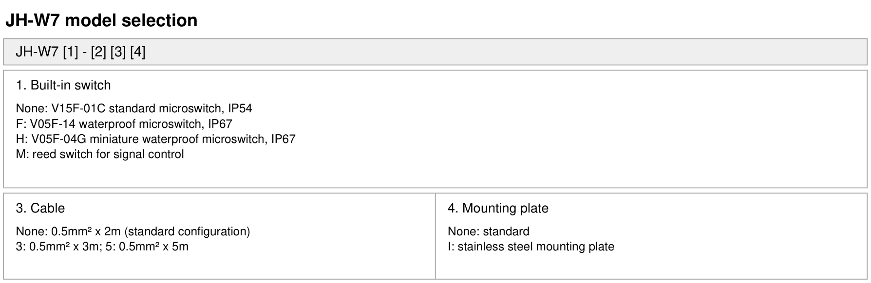
Options are for selection reference and cannot be freely combined. Confirm the complete model, contact arrangement, cable supply, cable length and connector before ordering.
Dimensions
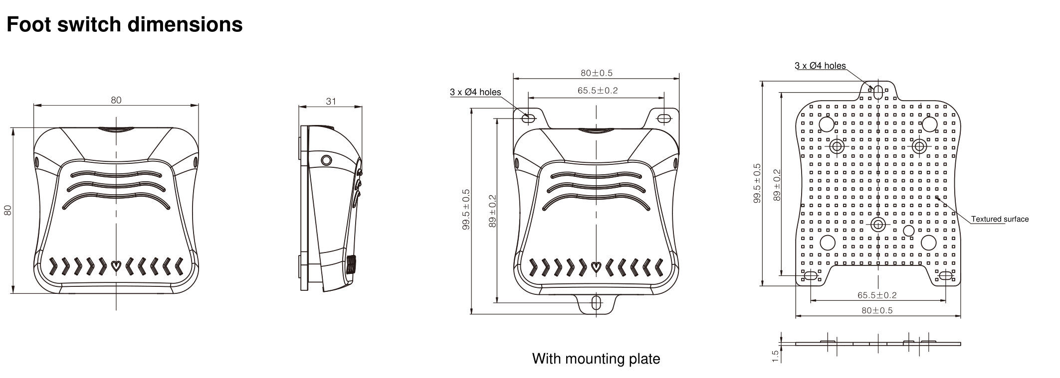
Body without mounting plate: 80 × 80 × 31mm. With mounting plate, the drawing shows 80 ±0.5mm width and 99.5 ±0.5mm length, 3 × Ø4mm mounting holes, 65.5 ±0.2mm and 89 ±0.2mm mounting callouts, and a 1.5mm plate thickness.
Wiring & Installation
1a denotes one normally-open contact; 1c denotes one changeover contact. The catalogue diagrams are reproduced below with English labels.

Wiring confirmation: the catalogue circuit diagram and its written wire-colour instructions disagree about the common conductor. Confirm COM, NO and NC against the supplied switch and model-specific wiring information before connection.
Optional mounting plate
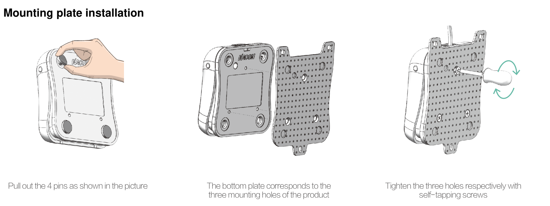
The catalogue installation sequence is: remove the four rubber feet, align the plate with the three mounting holes in the base, then secure the three positions with self-tapping screws.
Related Products
JH-W7 Series
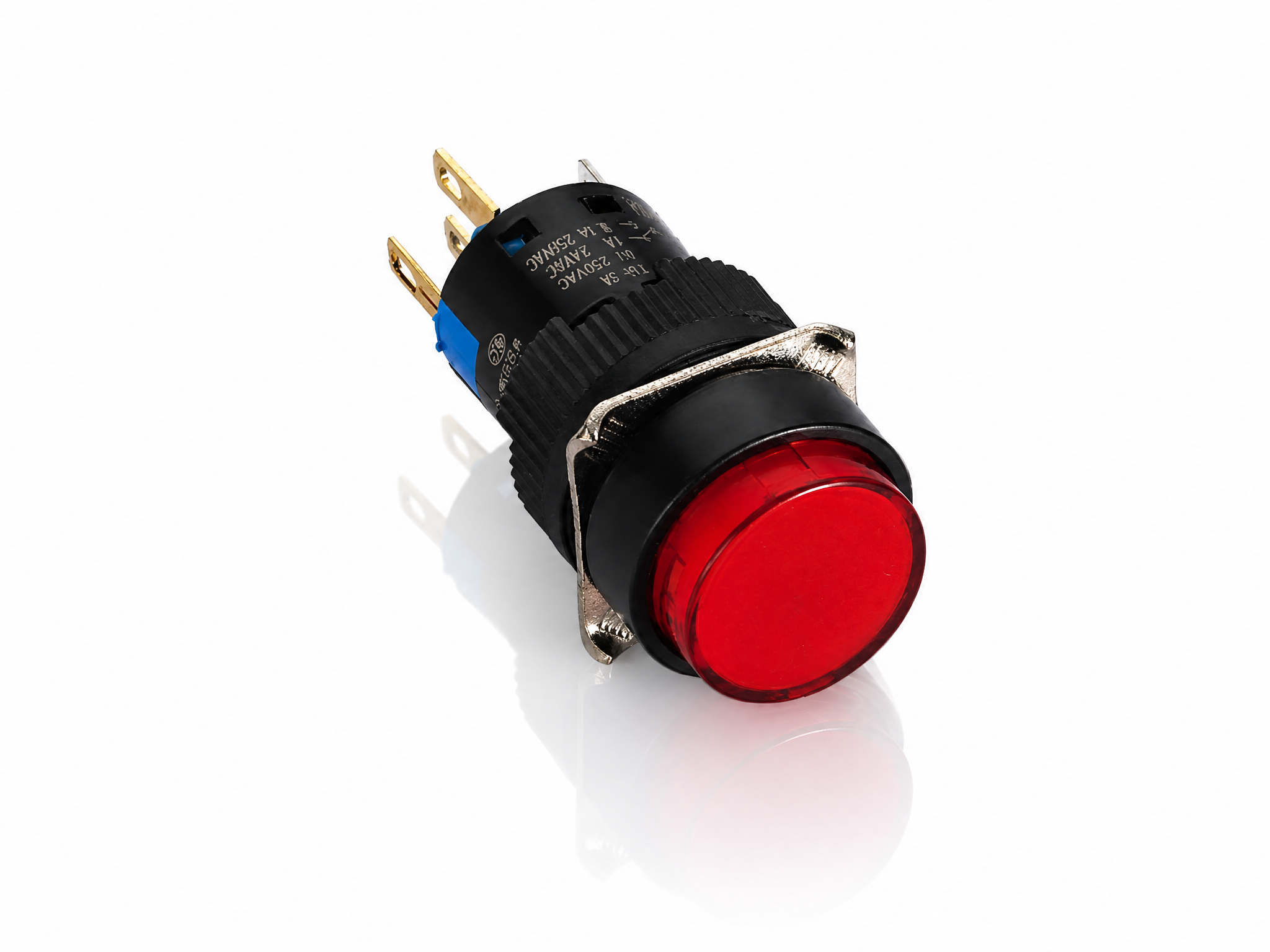 K16 16mm Round Illuminated Push Button Switch (Momentary)
- Model:K16-271, K16-272
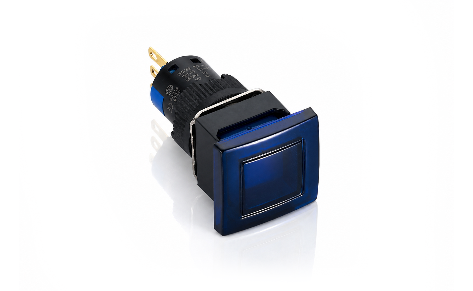 K16 16mm Mushroom Square Illuminated Push Button Switch (Momentary)
- Model:K16-981, K16-982
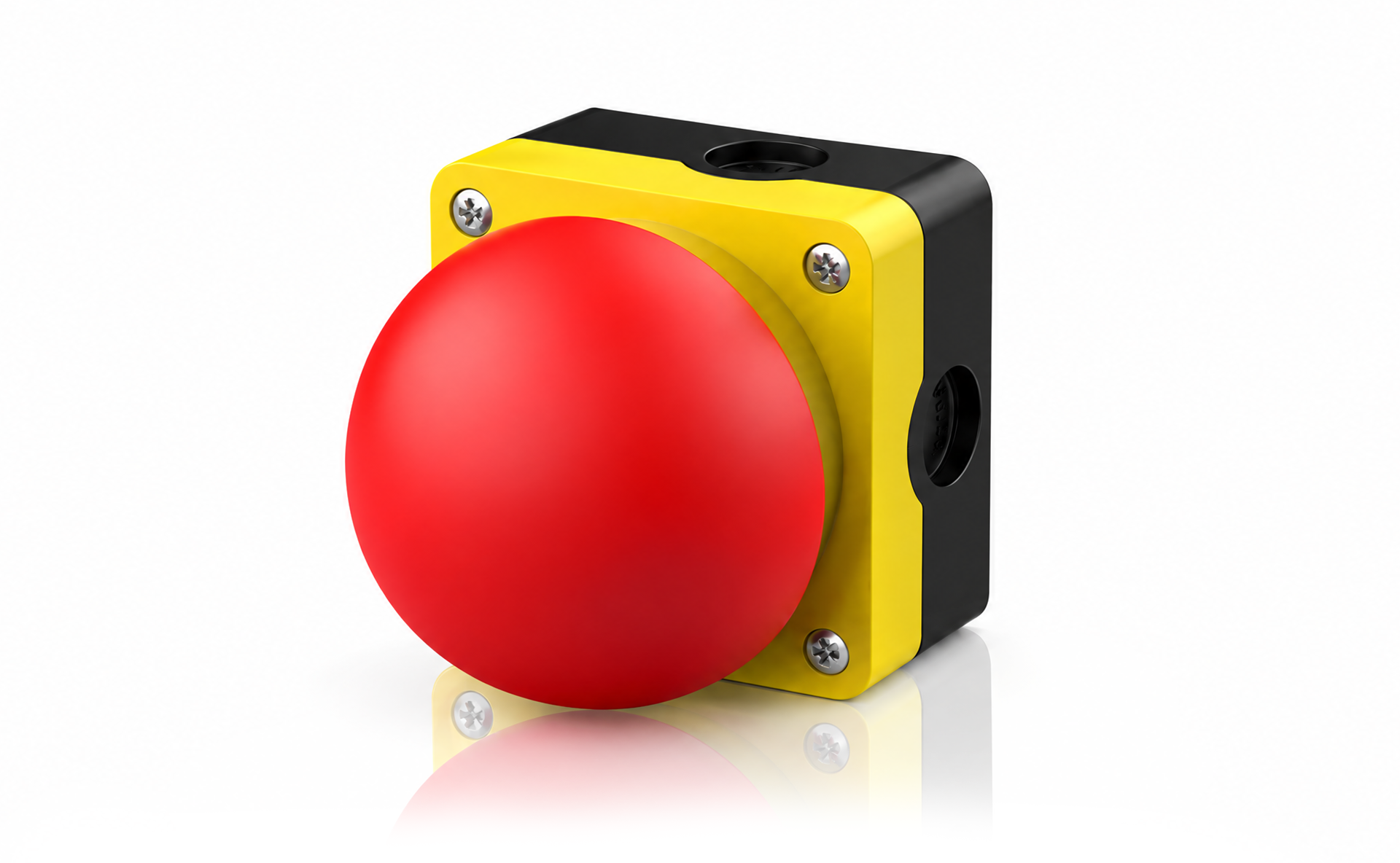 JHAK Mushroom-Head Palm Switch
- Model:JHAK
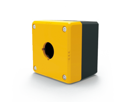 JHFB-1PY
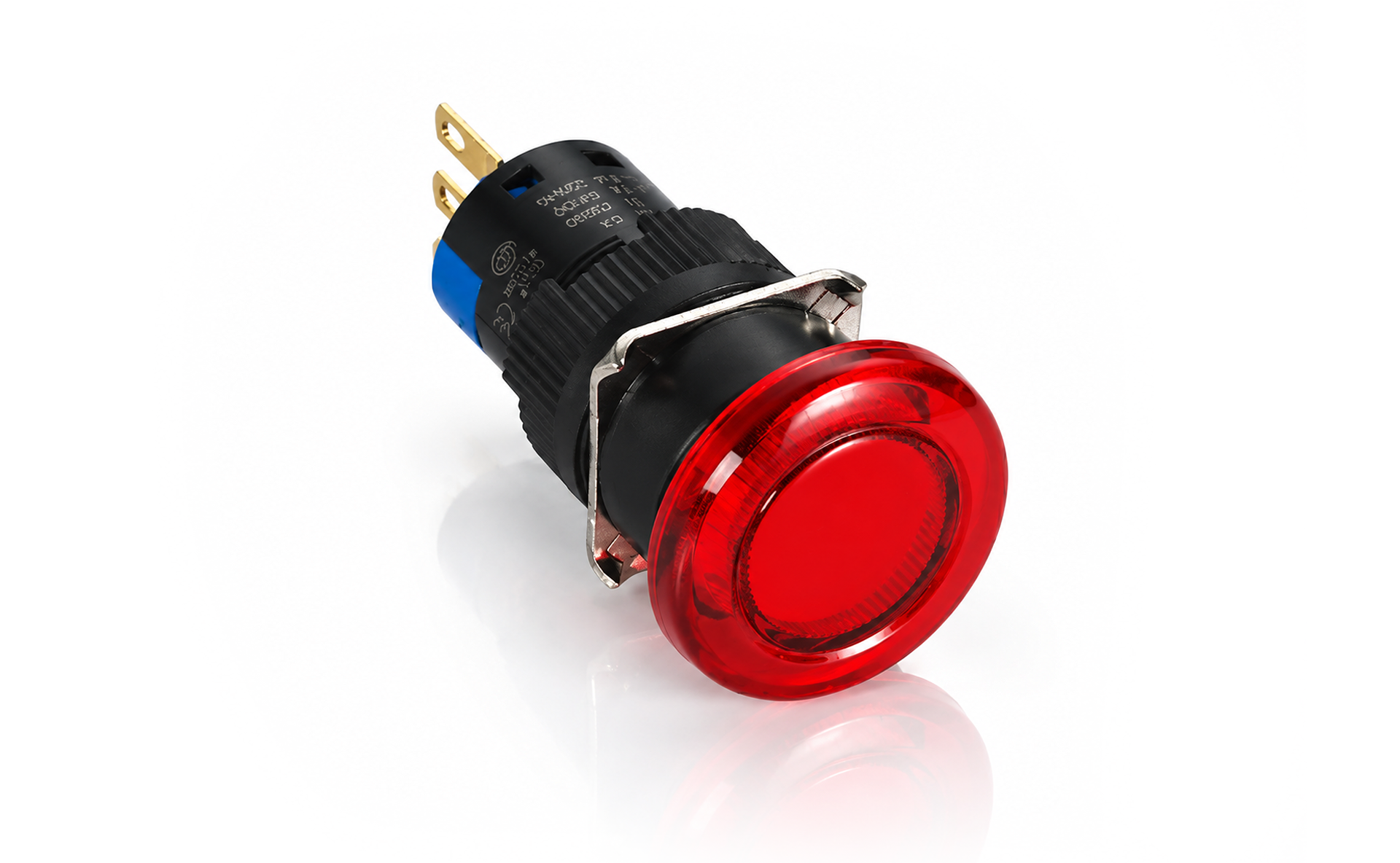 K16 16mm Mushroom Round Illuminated Push Button Switch (Momentary)
- Model:K16-971, K16-972
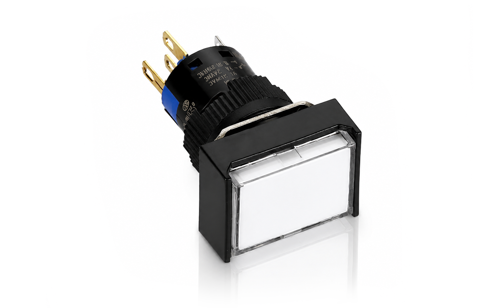 K16 16mm Rectangular Illuminated Push Button Switch (Momentary)
- Model:K16-291, K16-292
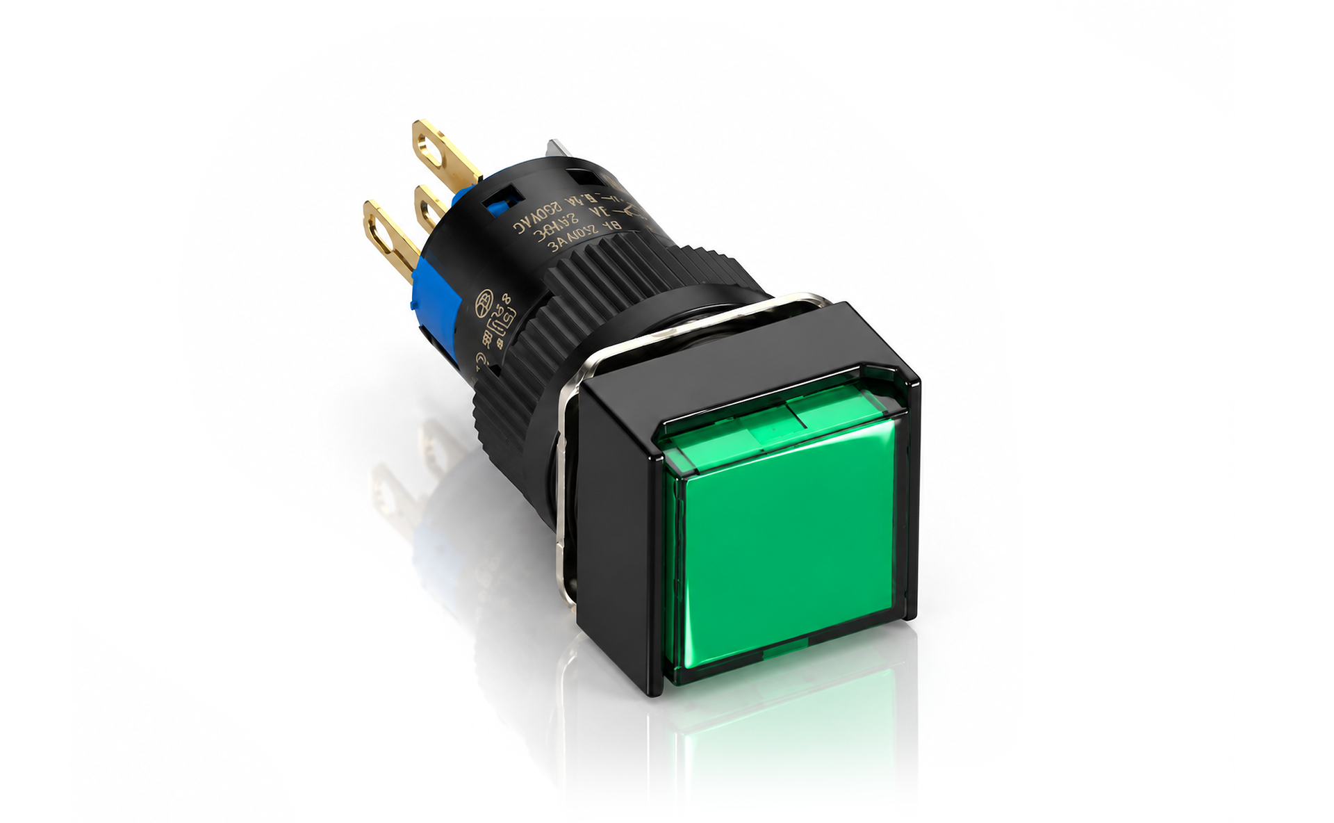 K16 16mm Square Illuminated Push Button Switch (Momentary)
- Model:K16-281, K16-282
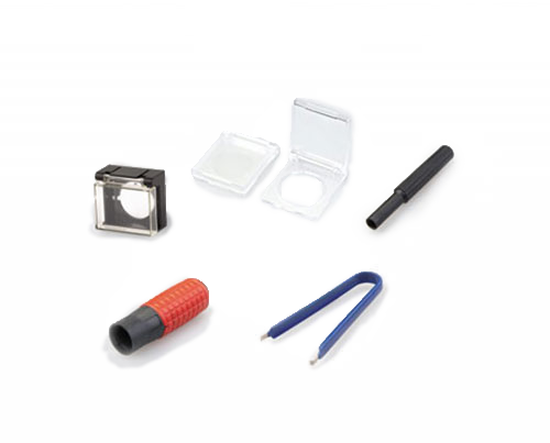 JH16 16mm Enclosure
- Model:JH16
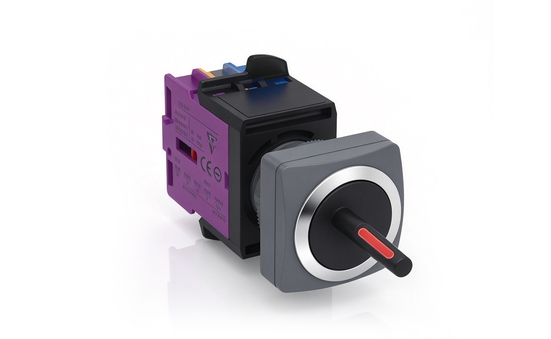 SK22-25 25mm Square Illuminated Selector Switch (3-Position Maintained)
- Model:SK22/25-5802-3, SK22/25-5811-3, SK22/25-5820-3, SK22/25-5802F-3, SK22/25-5811F-3, SK22/25-5820F-3
 HQ22 22mm Normally Open Contact Block (1NO)
- Model:HQ22
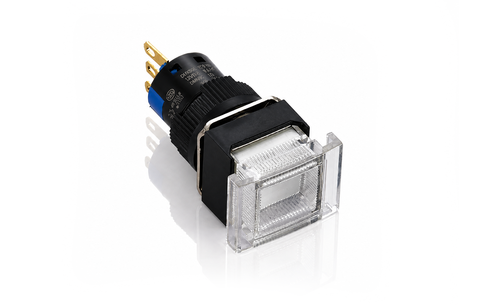 K16 16mm Mushroom Rectangular Illuminated Push Button Switch (Momentary)
- Model:K16-991, K16-992
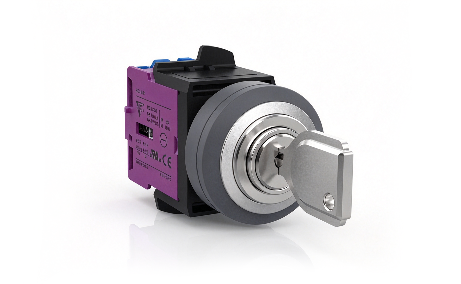 SK22-25 25mm Round Non-Illuminated Key Switch (3-Position Maintained)
- Model:SK22/25-7102-3, SK22/25-7111-3, SK22/25-7120-3, SK22/25-7102F-3, SK22/25-7111F-3, SK22/25-7120F-3
Contact us on WhatsApp
Choose how to continue. If WhatsApp Web is unavailable, open the app or copy our number.
+8613968766559