
JH-ZD3 Top-Protected Foot Switch
Model JH-ZD3
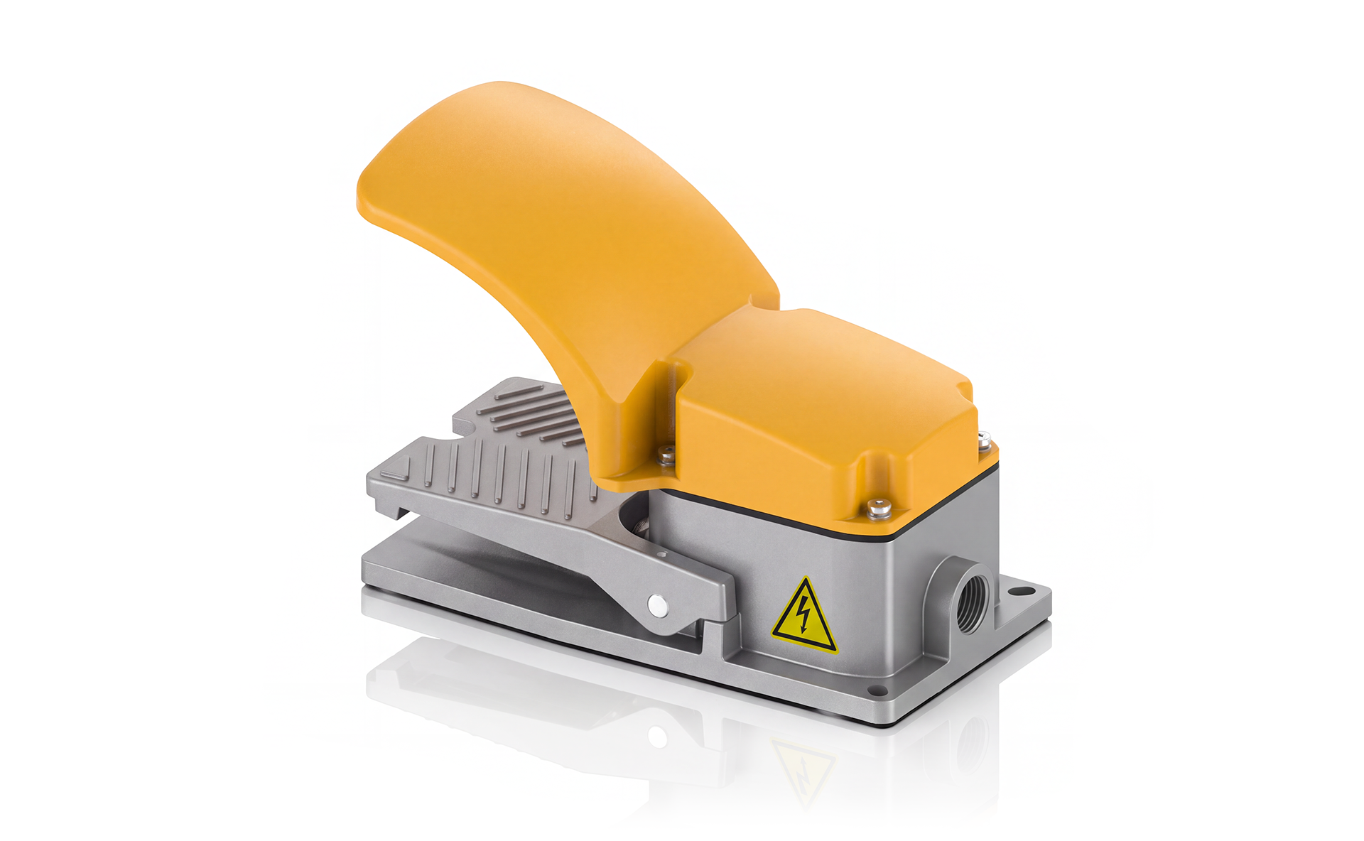
Cast aluminium foot switch with top guard; basic, 2C and self-locking versions.
- Series / ModelJH-ZD3
- HousingCast aluminium alloy
- Basic Contact Rating15A at 250VAC, resistive
- Contact Forms1C; custom 2C
- ActionBasic; custom self-locking
Description
The JH-ZD3 is a cast aluminium foot switch with a top protective guard and an anti-slip pedal. The catalogue lists a basic version, a custom two-contact version and a custom self-locking alternating version.
- Plastic-coated aluminium housing for abrasion and ageing resistance.
- Anti-slip pedal, thick spring and copper-core components.
- The guard covers the pedal to reduce accidental contact.
- Custom audio, DB serial and USB plug options; waterproof versions are available by request.
Specifications
| Series / Model | JH-ZD3 |
|---|---|
| Housing | Cast aluminium alloy |
| Basic Contact Rating | 15A at 250VAC, resistive |
| Contact Forms | 1C; custom 2C |
| Action | Basic; custom self-locking |
| Basic Switch | Z15G-10B |
| Self-locking Switch | VV15F-01C |
| Self-locking Rating | 10A; voltage not specified in the table |
| Operating Force | ≥20N |
| Cable Entry | G1/2 threaded hole |
| Protection Options | Waterproof version by request; numeric IP rating not stated |
Catalogue model variants
| Model | Version | Built-in switch | Contacts | Rating | Weight |
|---|---|---|---|---|---|
| JH-ZD3N | Basic | Z15G-10B | 1C | 15A, 250VAC (resistive) | 0.970kg |
| JH-ZD32N | Custom, two changeover contacts | Z15G-10B | 2C | 15A, 250VAC (resistive) | 1.005kg |
| JH-ZD3RN | Custom, self-locking alternating | VV15F-01C | 1C | 10A; voltage not stated | 0.960kg |
Listed cable configurations: JH-ZD3N uses grey RVV 0.5mm² × 3 cores × 2m; JH-ZD32N uses grey RVV 0.75mm² × 7 cores × 2m. Cable for JH-ZD3RN is specified separately. The catalogue states that cable is purchased separately.
Options are for selection reference and cannot be freely combined. Confirm the complete model, contact arrangement, cable supply, cable length and connector before ordering.
Dimensions
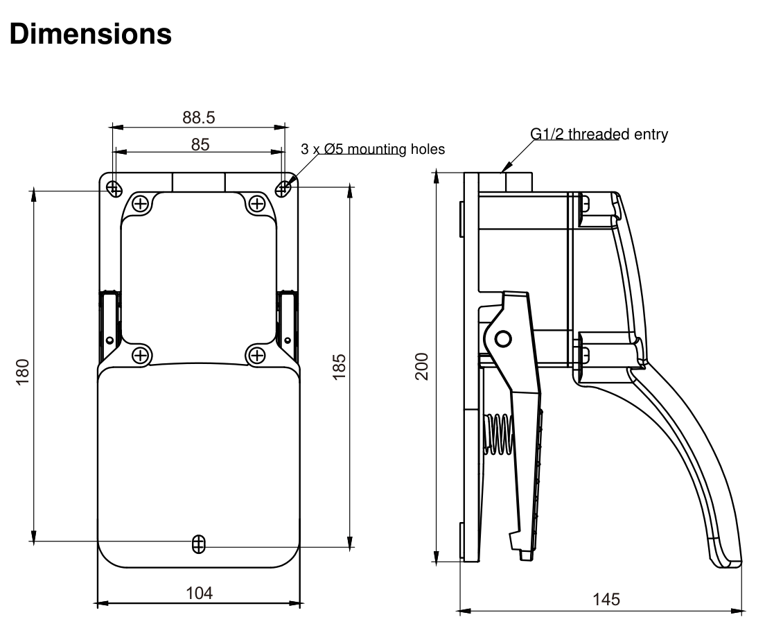
The catalogue drawing shows 185 × 104mm in the top view and 200 × 145mm in the side view, with 3 × Ø5mm mounting holes, 85 / 88.5mm transverse callouts, a 180mm longitudinal callout and a G1/2 cable entry. Use the dimensioned views below for the mounting layout.
Wiring & Installation
The catalogue shows one changeover contact (1C) and two changeover contacts (2C) for JH-ZD32N, marked SW1 and SW2. COM is the common terminal, NO is normally open and NC is normally closed.

Mount using the three Ø5mm holes shown in the dimensions drawing. Select the contact arrangement and action for the ordered model; the self-locking version has alternating action.
Related Products
JH-ZD3 Series
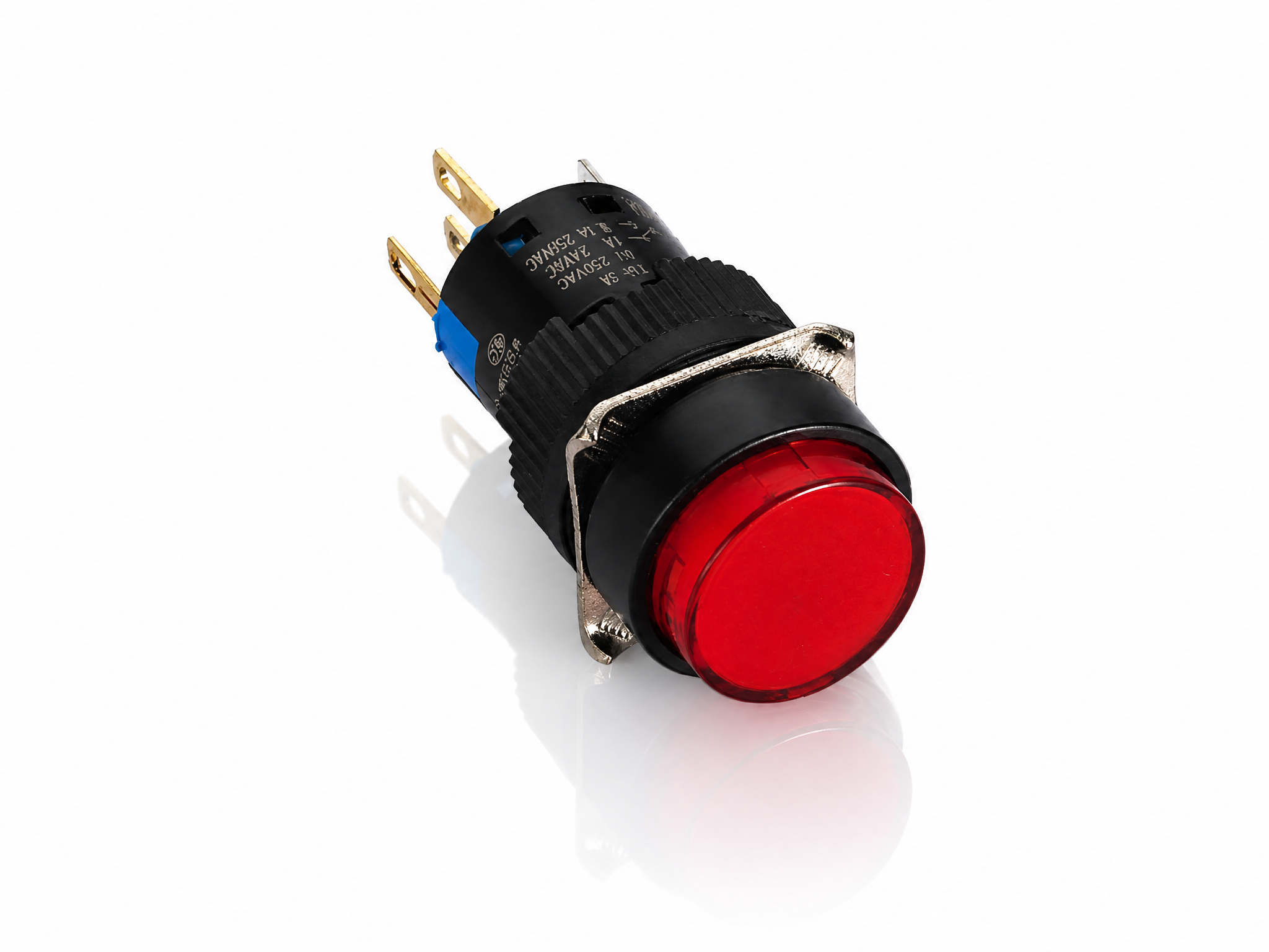 K16 16mm Round Illuminated Push Button Switch (Momentary)
- Model:K16-271, K16-272
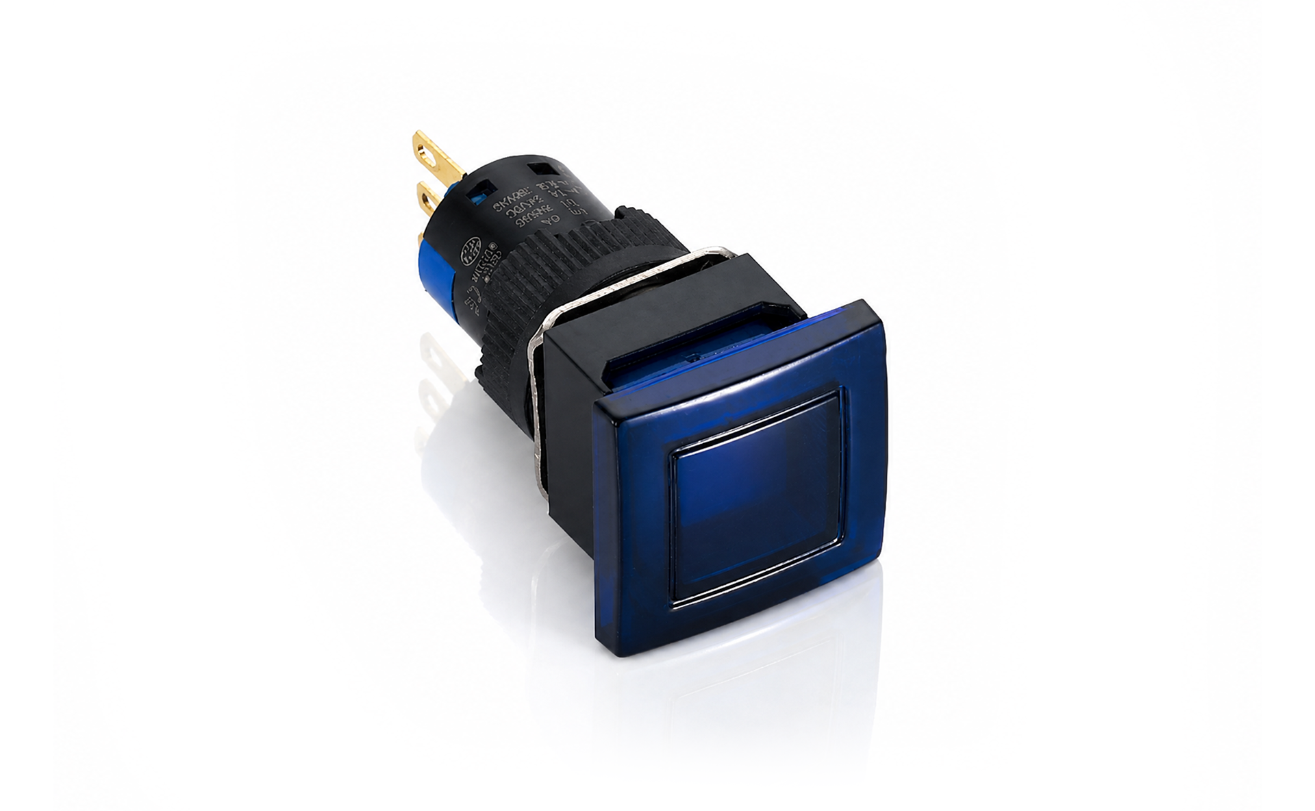 K16 16mm Mushroom Square Illuminated Push Button Switch (Momentary)
- Model:K16-981, K16-982
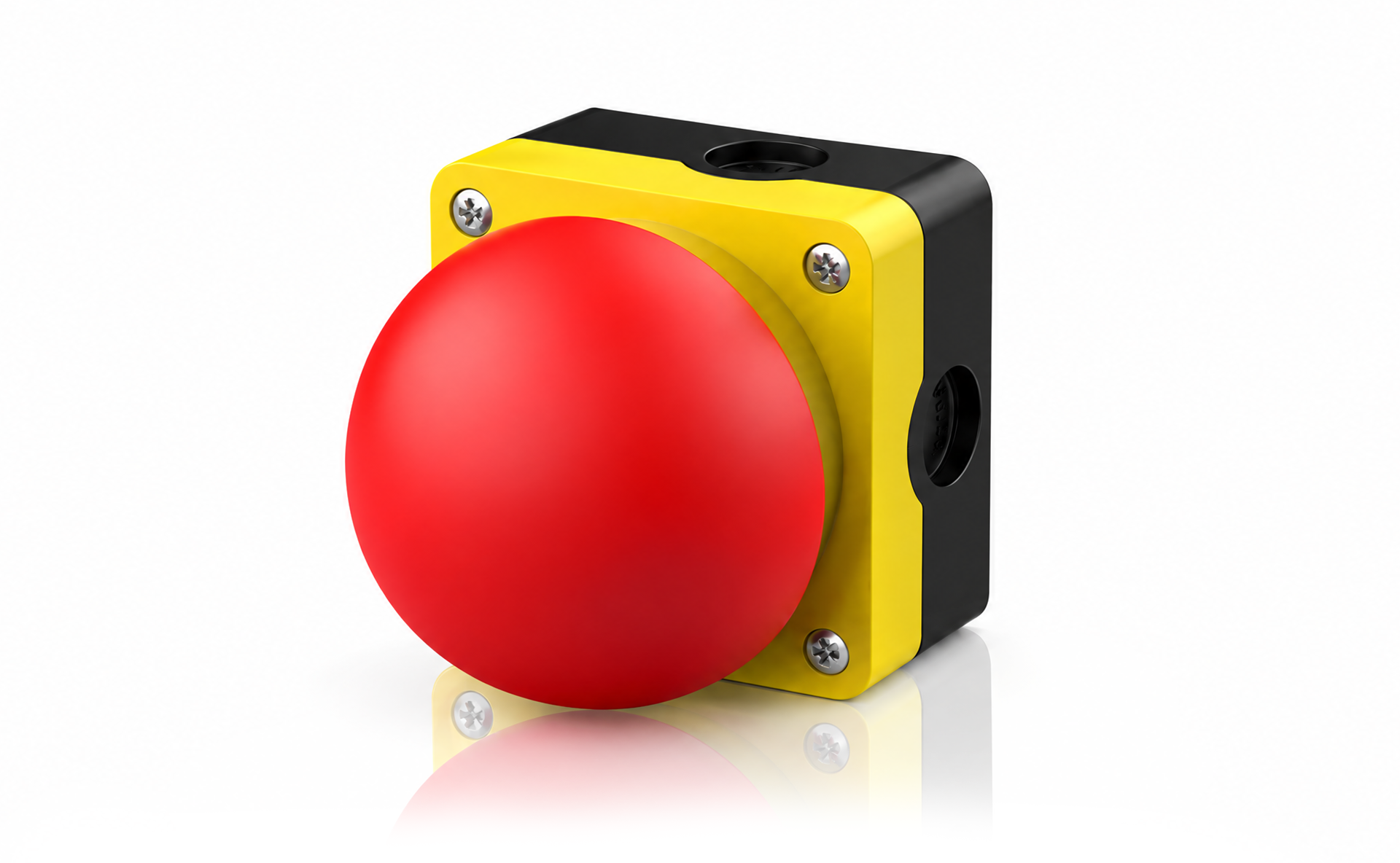 JHAK Mushroom-Head Palm Switch
- Model:JHAK
 JHFB-1PY
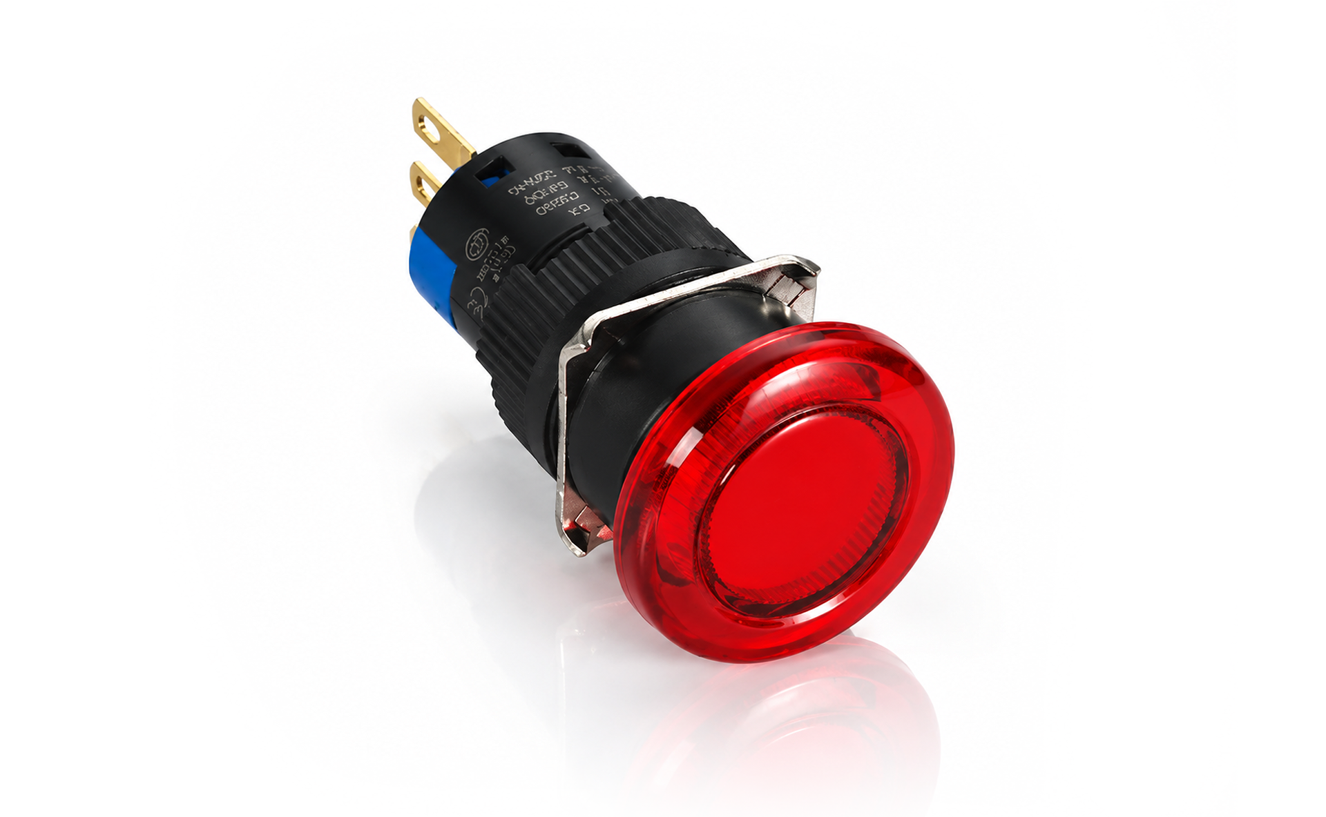 K16 16mm Mushroom Round Illuminated Push Button Switch (Momentary)
- Model:K16-971, K16-972
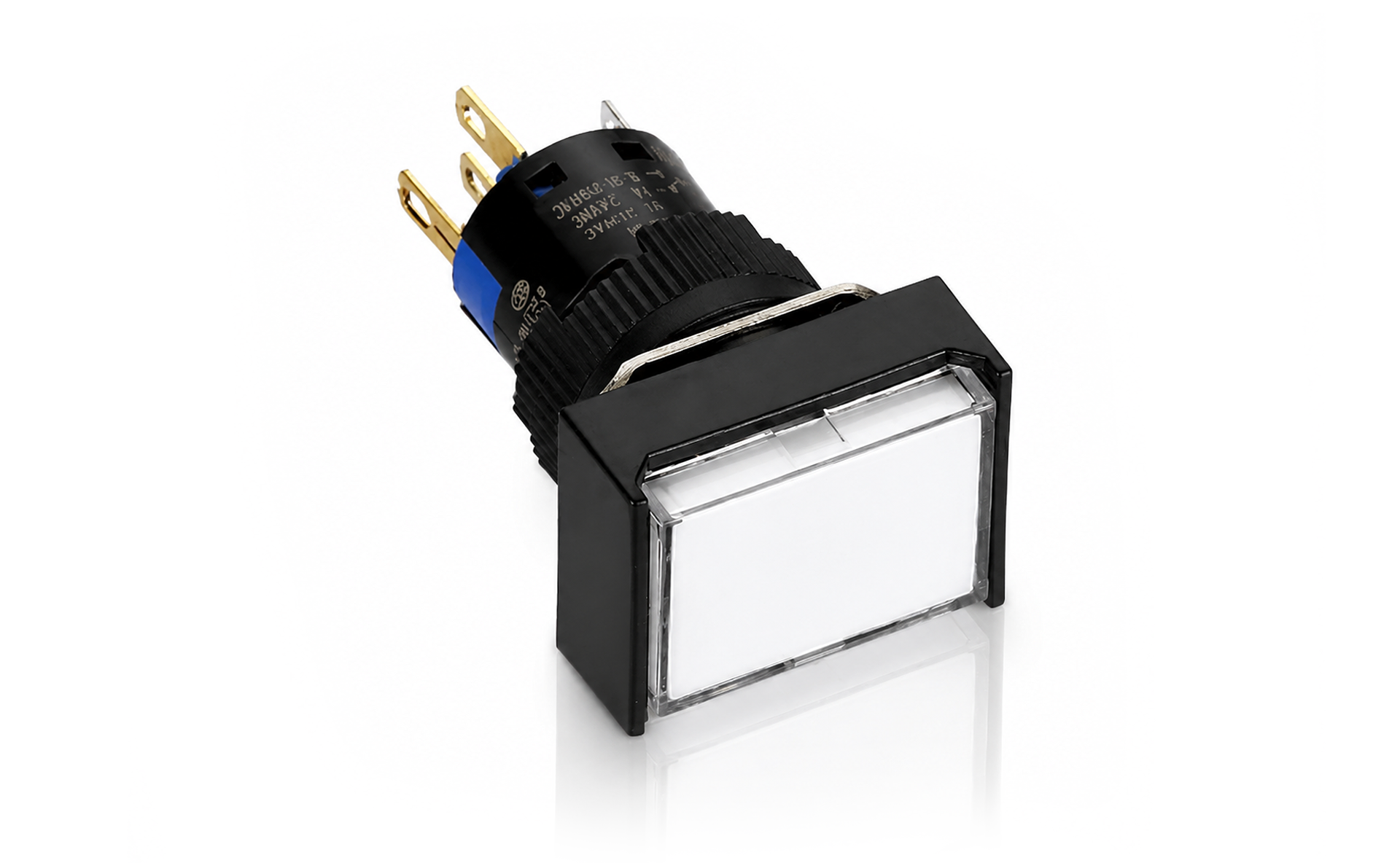 K16 16mm Rectangular Illuminated Push Button Switch (Momentary)
- Model:K16-291, K16-292
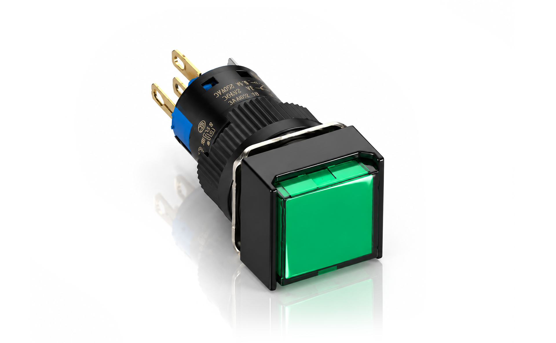 K16 16mm Square Illuminated Push Button Switch (Momentary)
- Model:K16-281, K16-282
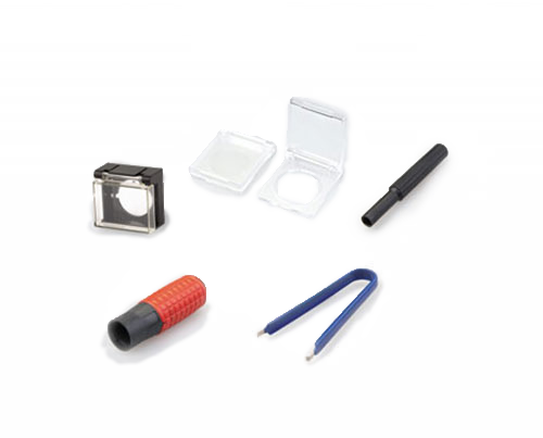 JH16 16mm Enclosure
- Model:JH16
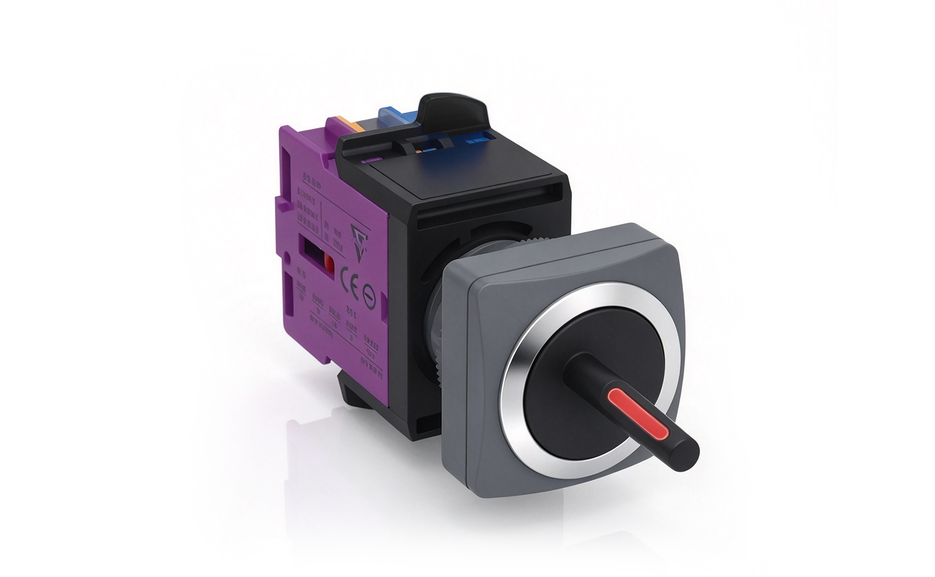 SK22-25 25mm Square Illuminated Selector Switch (3-Position Maintained)
- Model:SK22/25-5802-3, SK22/25-5811-3, SK22/25-5820-3, SK22/25-5802F-3, SK22/25-5811F-3, SK22/25-5820F-3
 HQ22 22mm Normally Open Contact Block (1NO)
- Model:HQ22
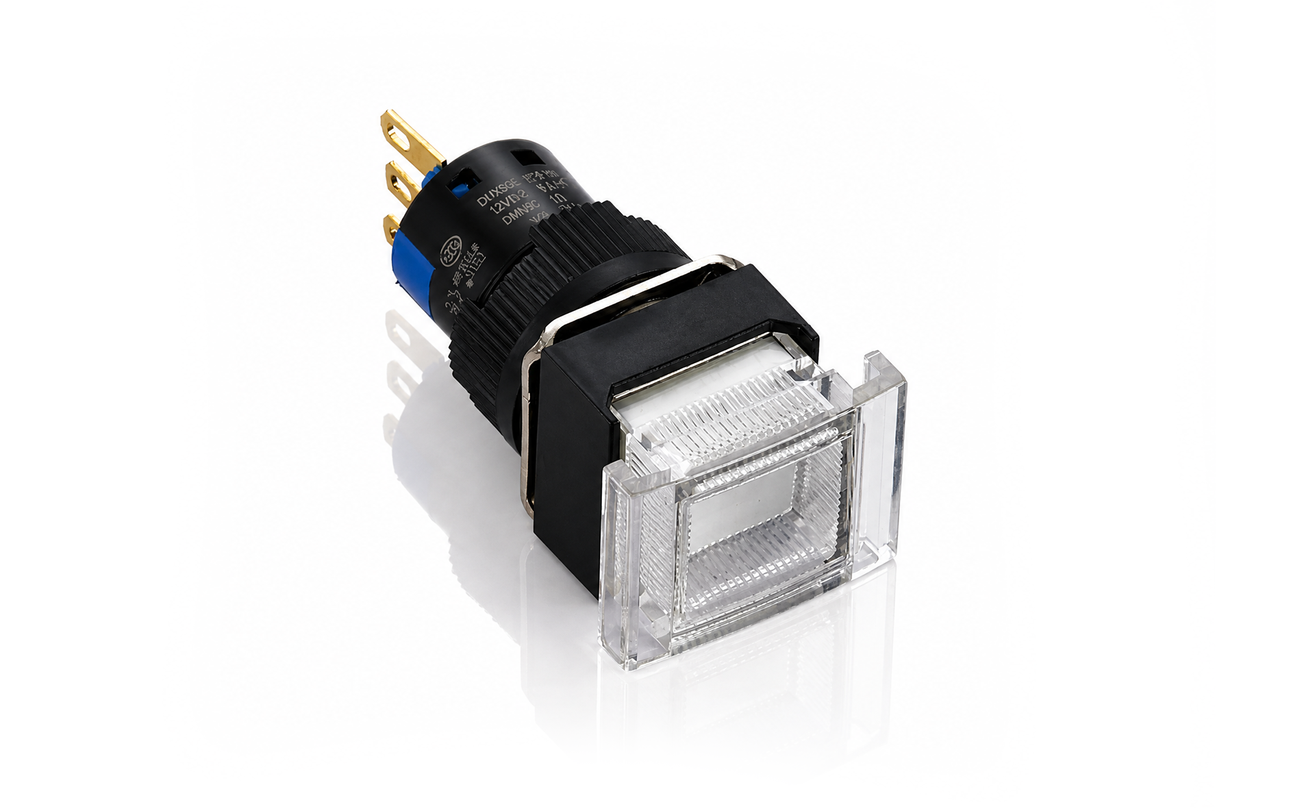 K16 16mm Mushroom Rectangular Illuminated Push Button Switch (Momentary)
- Model:K16-991, K16-992
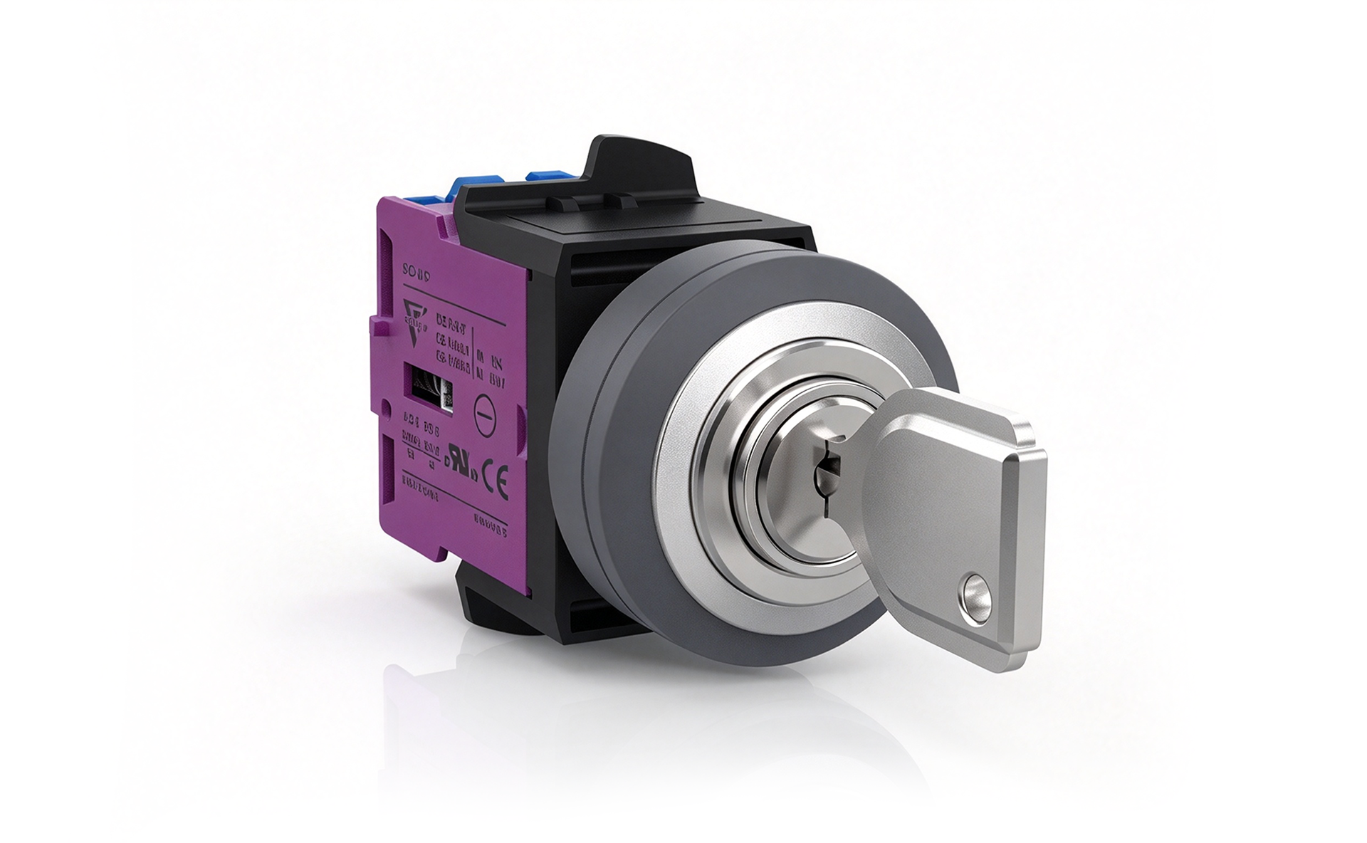 SK22-25 25mm Round Non-Illuminated Key Switch (3-Position Maintained)
- Model:SK22/25-7102-3, SK22/25-7111-3, SK22/25-7120-3, SK22/25-7102F-3, SK22/25-7111F-3, SK22/25-7120F-3
Contact us on WhatsApp
Choose how to continue. If WhatsApp Web is unavailable, open the app or copy our number.
+8613968766559