
Product guide
5-Pin Push Button Wiring: COM, NO, NC and LED
Understand a five-terminal illuminated push button, with separate contact and LED circuits, a low-voltage example and fault checks.
In this article
A common five-pin illuminated button contains two separate circuits: one changeover contact and one lamp. The pin positions are model-specific. Start with the exact terminal drawing, not the appearance of the rear connections.
Identify the contact and lamp terminals.
COM is the common contact. NO is open to COM when the button is unoperated; NC is closed. The two lamp terminals have their own voltage and AC/DC requirements. Follow any polarity markings and confirm whether the mechanism is momentary or latching.
Read the low-voltage example.
The diagram uses an isolated, protected 24V DC supply, a 24V DC-rated LED assembly and a small compatible DC indicator load. It shows circuit functions, not physical pin locations. It is not a motor or emergency-stop circuit.
Interactive functional diagram
What actually happens when the button is pressed?
Swipe the diagram sideways to follow the whole circuit — or press Explain step by step and it moves for you.
- 1+24V reaches COMThe protected feed stops at the common terminal.
- 2Pressing moves NC to NOThe blade leaves NC and closes onto NO.
- 3Load and LED switch onNO feeds both branches in parallel.
- 4Current returns to 0VThe loop closes, so current can flow.
Released: COM rests on NC, the NO circuit is open, and the load and button LED are off.
Functional 24V DC example. The rated LED assembly is connected in parallel with the example load. This shows circuit function, not physical pin positions, and it is not a motor or emergency-stop circuit. Combined load and lamp current must stay within the contact rating.

With the supply isolated, the protected positive feed goes to COM, NO supplies the load, and the load returns to 0V. The rated lamp connects between NO and 0V so that it lights with the switched output. NC remains unconnected and protected. Combined load and lamp current must stay within the contact rating.
Check the intended behaviour.
A momentary button returns when released; a push-on/push-off mechanism retains its contact state until the next operation. Connecting the lamp directly across the supply instead makes it a power indication. An NC contact alone does not provide a validated safety function.
Inspect before applying power.
Verify the model diagram, lamp rating, circuit protection and terminations. Check continuity only with the circuit isolated and disconnected. If operation is wrong, isolate the supply and recheck terminal identity and polarity; do not try a higher voltage.
Choosing for your application? Send the load details, operating action and LED voltage. Browse metal push buttons → or request the exact terminal drawing. Industrial loads may require a suitably designed relay or controller interface.
Information needed before using a wiring diagram
Use the example above to understand circuit functions. Obtain the selected button's drawing before translating those functions into physical terminal connections.
| Check | Information to record |
|---|---|
| Terminal identity | Exact model drawing showing contact and lamp terminals. |
| Lamp requirements | Rated supply, AC/DC type and any polarity markings. |
| Intended result | Momentary or maintained action, lamp behaviour and the actual switched load. |
Can I copy the physical pin positions from another five-pin button?
No. Five terminals do not establish a universal layout. Match the functions to the terminal drawing for the exact model and configuration.
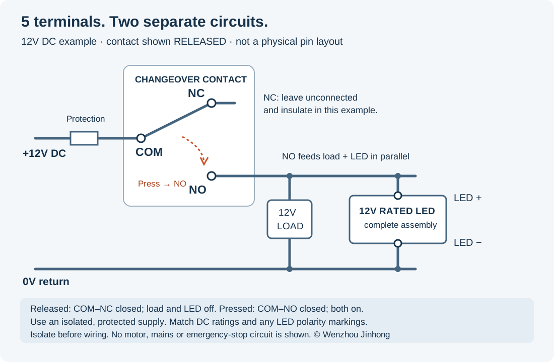
Original 12V DC COM / NO / NC / LED diagram
This second example uses an isolated, protected 12V DC supply, a complete 12V DC-rated LED assembly and a small compatible 12V DC indicator load. It shows an SPDT changeover contact plus a separate lamp. It is not a universal rear-view pinout.
| Terminal | Released | Pressed |
|---|---|---|
| COM | Connected to NC. | Connected to NO. |
| NO | Open to COM. | Closed to COM; supplies the example load and lamp. |
| NC | Closed to COM; unused and insulated in this example. | Open to COM. |
| LED + / LED − | Separate lamp circuit; off in this switched-output example. | 12V-rated lamp operates from NO to 0V; follow any polarity markings. |
Do not connect a bare LED directly to the supply: this example requires a complete voltage-rated lamp assembly. A 12V example requires 12V-rated components; changing the supply to 24V is not a troubleshooting step. Any wiring work must be performed with the supply isolated. The load plus lamp current must remain within the applicable DC contact rating, including the load type and inrush.
Troubleshooting before reconnecting power
| Symptom | Likely item to check | Safe next step |
|---|---|---|
| Lamp on all the time | Lamp may be across the supply rather than the switched NO output. | Isolate the supply and compare the intended lamp behaviour with the diagram. |
| Load on when released | The load may be on NC, or the mechanism may be latching. | With the circuit isolated and disconnected, check the terminal drawing and continuity. |
| Load switches but lamp stays dark | Lamp voltage/type, connection or polarity may be wrong. | Confirm the ordered lamp rating and polarity; never increase voltage to test it. |
| Neither lamp nor load operates | Open protection device, missing return or wrong common terminal. | Isolate and inspect the wiring; determine the cause before replacing protection. |
| Unexpected heating or repeated fuse operation | Short circuit, unsuitable load/inrush, loose termination or wrong rating. | Stop using the circuit and have the design and wiring checked; do not bridge protection. |
J19-C and J12: compare the actual contact version
| Product | Current published contact information | What to request |
|---|---|---|
| J19-C-271 illuminated ring button | 19mm; the listed variant is 1NO. | Exact terminal drawing and lamp voltage option. Do not assume COM/NO/NC. |
| J12-271 illuminated ring button | 12mm; the listed variant is 1NO. | Confirm whether an ordered five-terminal changeover version exists before using this diagram. |
| J19 illuminated ring button | The page lists 1NO+1NC and 2NO+2NC versions. | Confirm whether contacts have a common terminal or separate pairs; contact count alone does not prove five pins. |
Browse metal push buttons or request a verified terminal drawing for your exact order. Provide the model, operating action, voltage, load type/current and desired lamp behaviour. None of these links is a claim that every variant uses the five-terminal arrangement above.
Explore the products
Catalogue examples from the ranges discussed. Open a model to check its configuration and technical details.

J16-E Illuminated Ring Flat Head Metal Push Button Switch (Momentary)
View model
J19 Illuminated Ring Flat Head Metal Push Button Switch (Momentary)
View model
K16 16mm Round Illuminated Push Button Switch (Momentary)
View model