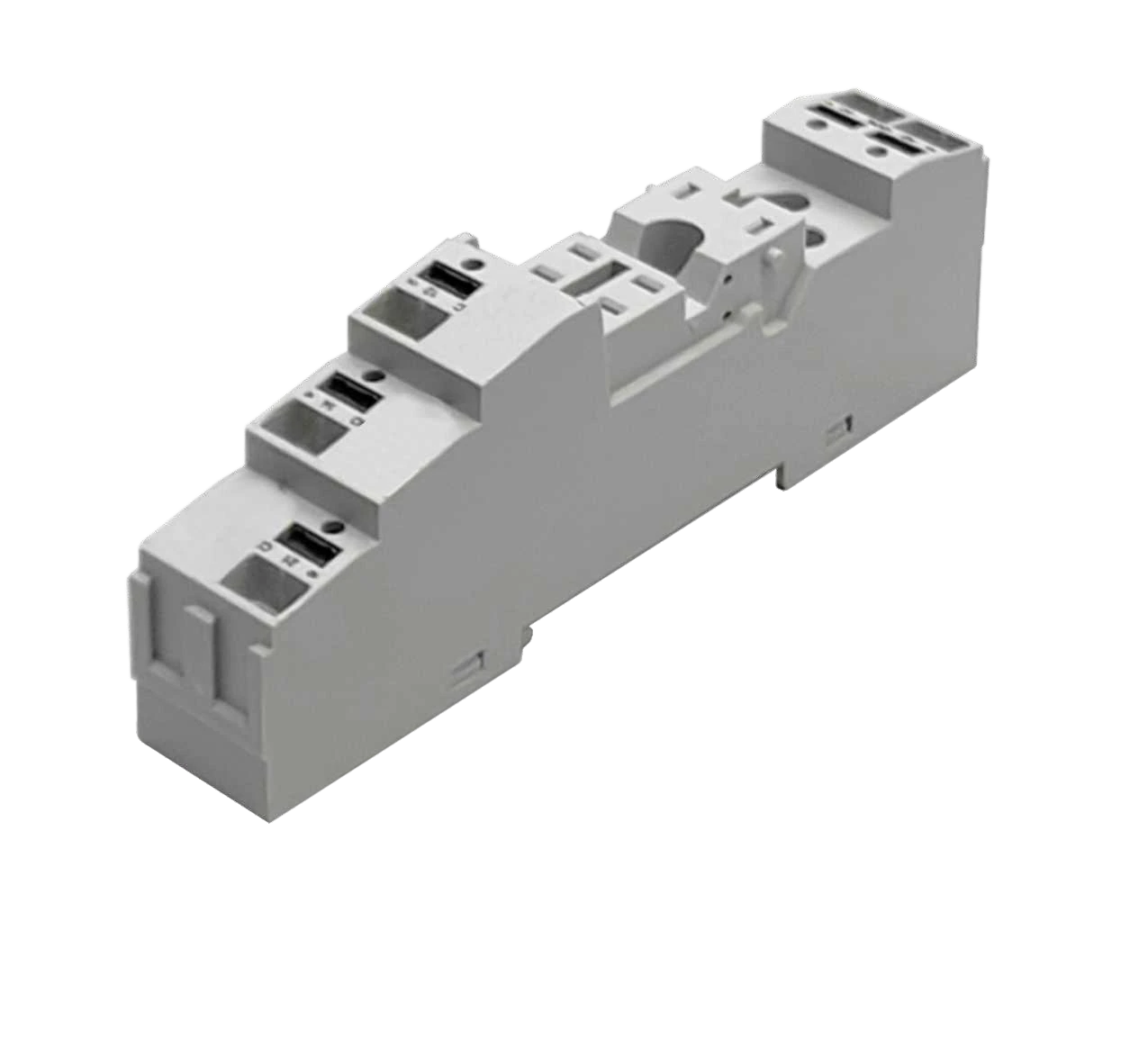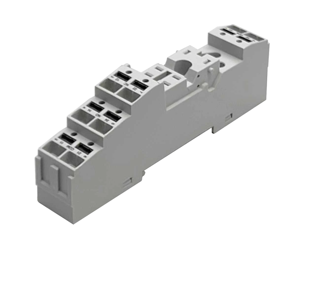
A relay can click while the monitoring input stays unchanged. The coil operates the mechanism; the contacts route the separate signal. Choose the contact function first, then match the socket interface and coil supply to the panel.
In this worked example, a panel provides 24 VDC control power and needs one contact to select between two monitoring inputs. The NC path serves the off-state input and the NO path serves the on-state input. The 24 VDC value is a project requirement; the relay’s full coil option still needs confirmation.
1. Turn the required signal into a relay and socket shortlist.
The required function is one changeover contact: a common terminal switches between NC and NO. You may also see it called Form C, 1CO or SPDT. In the ZJ157F ordering system, 1P identifies one Form C pole; 2P provides two.
| Socket candidate | Relay interface | Decision for this example |
|---|---|---|
| 157F-1Z-C5 | 1CO / SPDT; 5-pin | One changeover circuit: matches the required interface |
| 157F-2Z-C5 | 2CO / DPDT; 8-pin | Two changeover circuits: a different interface, unnecessary here |
Both sockets use push-in connections and support 35 mm DIN-rail or panel mounting. The pin counts describe the relay interface, not every conductor opening.

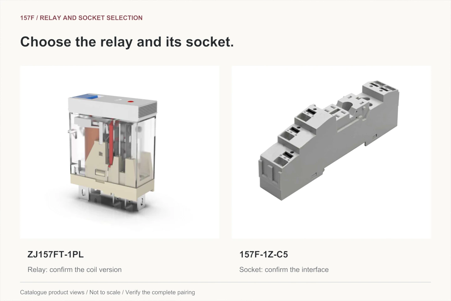
The shortlist is the one-pole ZJ157FT-1PL relay variant and 157F-1Z-C5 socket. Confirm the complete codes and approved pairing, including the required coil option, before ordering.
2. Keep the coil supply and monitored circuit on separate lines.
The example’s control output supplies 24 VDC. Choose the corresponding documented coil version and check that the output can drive it. A contact or socket voltage rating cannot substitute for the coil rating.
| Selection record | Entry for the illustrative panel |
|---|---|
| Contact function | One changeover pole; use both off-state and on-state paths |
| Coil requirement | 24 V DC from the panel control output; exact ordering suffix to be confirmed |
| Switched circuit | Monitoring interface; take each input's voltage, current and any inrush from its data |
| Functional shortlist | ZJ157FT-1PL relay variant and 157F-1Z-C5 socket |
The monitoring interface matters even if its input current is small. Check the applicable minimum switching requirement as well as maximum load capability; a relay selected for a large resistive load is not automatically suitable for every small signal. For a solenoid, lamp or motor application, its starting behavior and load category would change this assessment.
LED and diode options can make coil polarity important. Follow the fitted option’s drawing; an indicator response alone does not prove contact closure. Figure 3 helps identify the test button, LED and pin interface.

3. Use the function map to write the acceptance test.
The ZJ157FT-1PL source drawing identifies coil terminals 1 and 5, COM 4, NC 2 and NO 3. For the illustrative monitoring function, the settled-state test sheet is:
| Coil condition | Required contact result | Expected monitor path |
|---|---|---|
| De-energised | 4–2 closed; 4–3 open | NC path available; NO path absent |
| Energised at the selected rated supply | 4–2 open; 4–3 closed | NO path available; NC path absent |
| Supply removed after operation | Returns to 4–2 closed; 4–3 open | Returns to the off-state path |
This completes the functional result: one coil command changes the monitoring interface between two defined signal paths. It does not prove that the monitored machine is running; the system designer chooses what the command represents and how the monitor interprets it.
Use the complete relay and socket drawings to assign physical terminals and viewing direction, including coil polarity and fitted options. The animation and test table describe function only.
4. Check the assembly, then verify the planned result.
Compare the load requirements with the relay, socket, conductors and accessories under the actual installation conditions. A higher socket rating cannot increase relay switching capacity. The final selection also needs the specified retention, mounting clearance and access for removal.
Before wiring, isolate the relevant supplies and verify the work area is de-energised. Prepare the conductors to the selected socket's current wire-type, cross-section, strip-length and ferrule instructions. Label coil and contact circuits separately and check conductor retention.
During controlled commissioning, a qualified person compares the off, on and return states with the acceptance table. If the relay clicks but the monitor stays unchanged, record which observation fails before deciding what to investigate:
| Observed symptom | Focus and comparison |
|---|---|
| Relay operates; monitor stays unchanged. | Contact path and monitor input. Compare contact states with the off/on table, then trace the assigned signal path. A click alone does not establish contact closure. |
| Monitor shows the opposite state. | NC/NO assignment and input interpretation. Compare the actual signal path with the intended off/on record before changing connections. |
| Test button works; controller command does not. | Electrical coil drive. Compare the output and coil requirements, including supply and fitted-option polarity. Manual actuation does not validate the electrical drive. |
These observations narrow the investigation; they do not identify a failed part by themselves. Use the site’s approved test procedure and test method. Never use continuity or resistance mode on an energised circuit; isolate all connected sources and verify absence of voltage before those checks.
Frequently asked questions
Can two relay contacts be paralleled to increase capacity?
Do not claim doubled capacity: the contacts do not necessarily close or open simultaneously. Select a component with a documented rating for the required load instead.
Can the test button replace electrical commissioning?
It can help inspect contact action, but it does not demonstrate that the controller drives the selected coil correctly or that the full circuit behaves as required. Verify the electrical command and return behavior as well.
Request the two parts as a matched selection.
Compare the ZJ157F relay range, 157F-1Z-C5 one-pole socket and 157F-2Z-C5 two-pole socket. The example calls for a one-pole, five-pin combination and a verified 24 V DC coil version.
Ask JINHONG for a matched selection and current drawings. Include the shortlist, quantity, coil supply, monitoring-input data, installation temperature, conductor details and required approvals. Send the functional test sheet so the intended off/on behavior is clear.
Continue reading
Explore the products
Compare one- and two-pole socket options. Check the matching relay, terminal arrangement and installation details before ordering.