
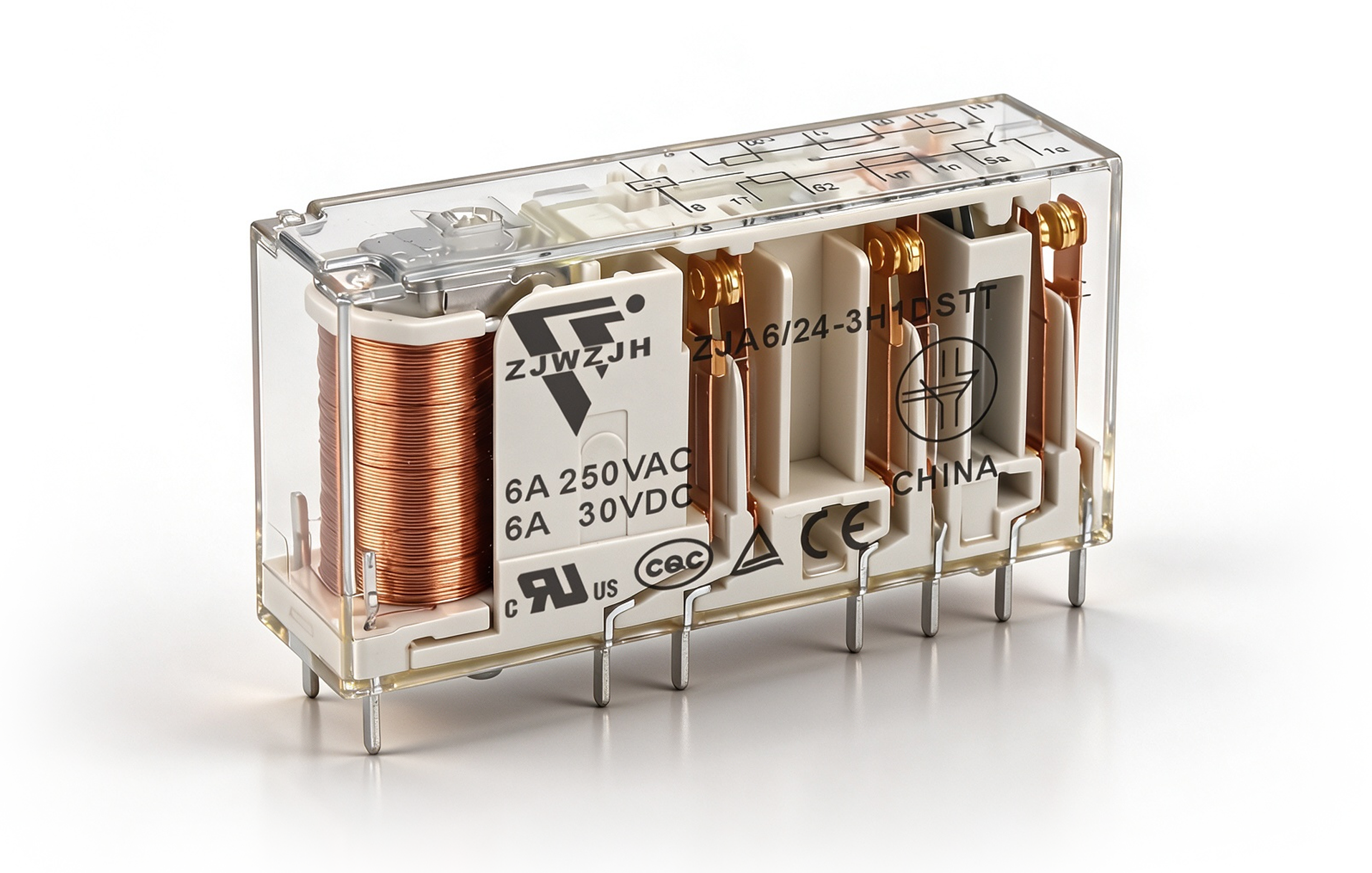
ZJA4 Force-Guided Relay
Model ZJA4
4-pole (2NO+2NC / 3NO+1NC), 6A, IEC 61810-3 guided contacts, AgSnO2, 10kV isolation
- Configuration4-Pole
- ModelZJA4
- Contact arrangement2NO + 2NC (2H2D)3NO + 1NC (3H1D)
- Contact load (resistive)6 A 250 V AC / 30 V DC
- Minimum load5 V DC 10 mA
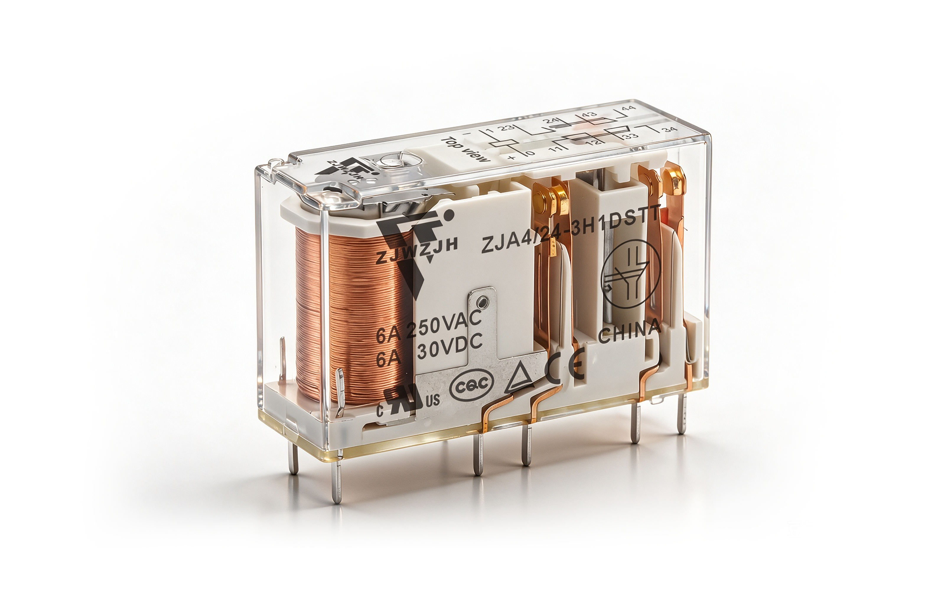
Product Information
The ZJA4 is a 4-pole force-guided (mechanically linked) safety relay from the ZJA series. Its forcibly guided contact structure to IEC 61810-3 (Type A) guarantees that NO and NC contacts can never be closed at the same time, providing a reliable, fault-detecting feedback (mirror) contact for machine-safety circuits.
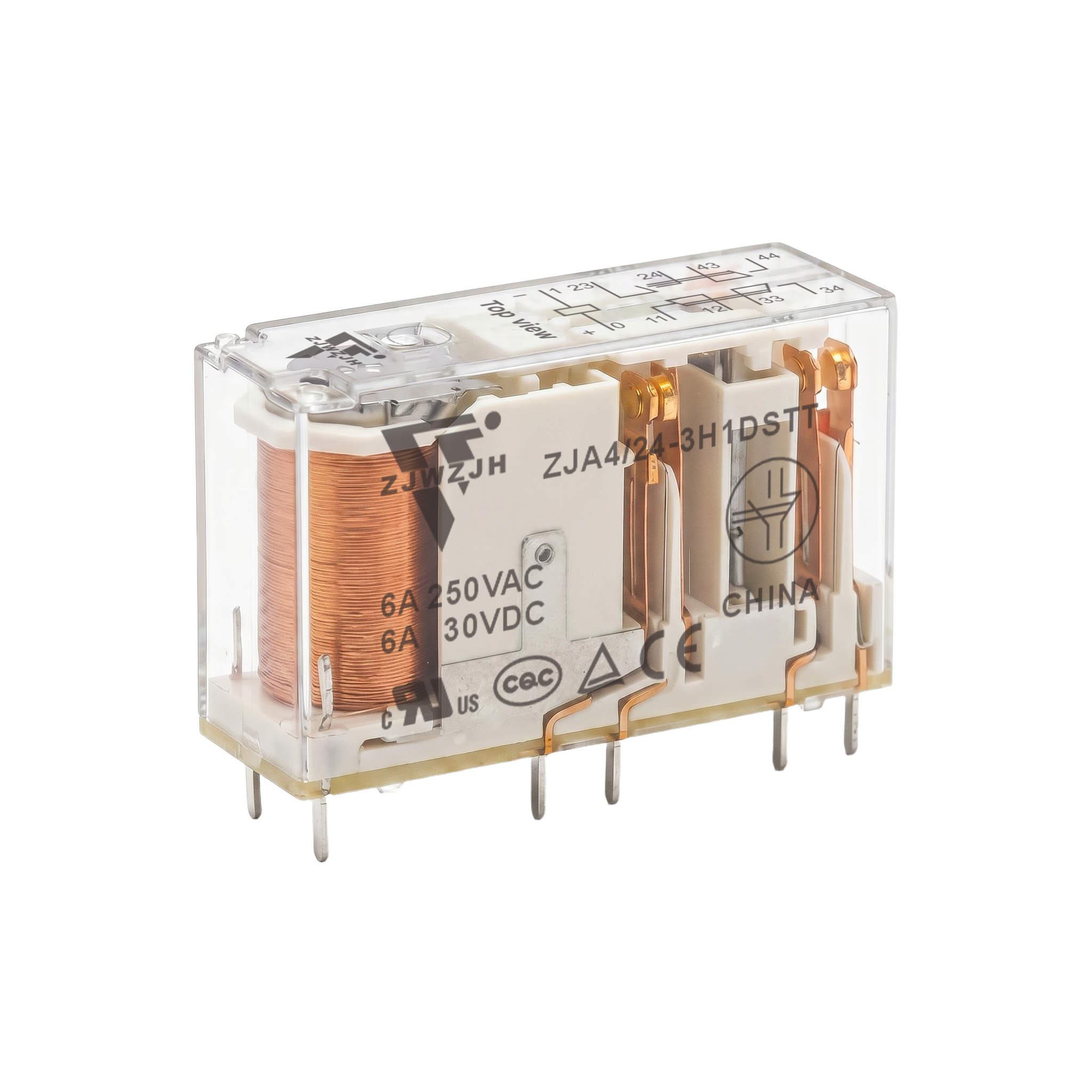
Key features
- 4-pole contact arrangements — 2NO + 2NC (2H2D) or 3NO + 1NC (3H1D)
- Forcibly guided (mechanically linked) contacts per IEC 61810-3, Type A structure
- 6 A switching capability — 6 A 250 V AC / 30 V DC (resistive)
- Low input power — 360 mW coil
- High insulation — 10 kV surge (input–output), 4000 V AC dielectric (coil–contacts)
- AgSnO₂ contacts — gold-plated version available (suffix R)
- Wide DC coil range — 5 / 6 / 9 / 12 / 18 / 24 / 36 / 48 / 110 V DC
- PCB terminals; flux-proofed; body approx. 40 × 13 × 24 mm, ~20 g
- UL Class F insulation system; CE, TÜV Rheinland, cULus; RoHS
Typical applications:
Safety relay modules, emergency-stop and guard/door-monitoring circuits, light-curtain and two-hand control, and machine-safety controllers — wherever forcibly guided (mirror) feedback contacts are required.
Ordering (select code): ZJA4 / {coil V DC} — {2H2D | 3H1D} T {R} — T = AgSnO₂ contact material, R = gold-plated contacts; e.g. ZJA4/24—2H2DT (24 V DC coil).
Manufactured by Wenzhou Jinhong (WZJH), a China relay manufacturer — OEM / ODM welcome.
Characteristics
| Configuration | 4-Pole |
| Model | ZJA4 |
| Contact arrangement | 2NO + 2NC (2H2D)3NO + 1NC (3H1D) |
| Structural classification | Type A force-guided (mechanically linked) contacts — IEC 61810-3 |
| Contact material | AgSnO₂ (gold-plated version available, suffix “R”) |
| Contact load (resistive) | 6 A 250 V AC / 30 V DC |
| Minimum load | 5 V DC 10 mA |
| Contact resistance | ≤100 mΩ (1 A 6 V DC) |
| Max. switching voltage | 400 V AC / 30 V DC |
| Max. switching current | 6 A |
| Max. switching power | 1500 VA / 180 W |
| Electrical endurance | 1×10⁵ operations (1NO, 6 A 30 V DC resistive) · 1×10⁵ operations (1NO, 6 A 250 V AC resistive) — room temp., 1 s on / 9 s off |
| Mechanical endurance | 1×10⁷ operations |
| Coil power | 360 mW |
| Coil voltage | 5 / 6 / 9 / 12 / 18 / 24 / 36 / 48 / 110 V DC |
| Operate / release time | ≤20 ms / ≤20 ms |
| Insulation resistance | 1000 MΩ (500 V DC) |
| Dielectric strength | 4000 V AC 1 min (coil–contacts) · 1500 V AC 1 min (open contacts) · 2500 V AC 1 min (contact groups 7-8 / 9-10), 4000 V AC 1 min (other groups) |
| Surge voltage | 10 kV (1.2/50 µs, coil–contacts) · 5 kV (1.2/50 µs, between contact groups) |
| Vibration resistance | NO/NC: 10–55 Hz 1.5 mm double amplitude · NO: 55–200 Hz, 98 m/s² · NC: 55–200 Hz, 49 m/s² |
| Shock resistance | 100 m/s² (stability) / 980 m/s² (strength) |
| Humidity | 5–85% RH |
| Termination | PCB terminals |
| Encapsulation | Flux-proofed |
| Body size (L × W × H) | approx. 40 × 13 × 24 mm |
| Weight | ~20 g |
| Approvals | CE · TÜV Rheinland · cULus; UL Class F insulation system; RoHS |
Specifications
Wiring diagrams (bottom view) — 4-pole contact arrangements 2NO + 2NC (2H2D) or 3NO + 1NC (3H1D); DC coil on terminals 1–0. Performance curves: maximum switching capacity (AC / DC resistive), electrical endurance (1NO, 250 V AC resistive, room temp., 1 s on / 9 s off — typical values) and coil temperature rise (0 A / 6 A load, at 85 °C and room temperature).
 ZJA4 — 2H2D2NO + 2NC wiring (bottom view)🔍 Click to enlarge
 ZJA4 — 3H1D3NO + 1NC wiring (bottom view)🔍 Click to enlarge
 Maximum switching capacityAC / DC resistive load🔍 Click to enlarge
 Electrical endurance1NO · 250 V AC resistive · typical🔍 Click to enlarge
 Coil temperature risevs. % of rated coil voltage🔍 Click to enlarge
Dimensions
Dimensions (mm) — PCB-terminal safety relay, body approx. 40 × 13 × 24 mm (L × W × H), terminal grid 5.08 / 10.16 mm pitch; PCB layout (bottom view) with 10 × Φ1.4 holes. Unless noted, tolerances: ±0.2 mm (≤1 mm), ±0.3 mm (1–5 mm), ±0.4 mm (>5 mm); PCB layout ±0.1 mm.
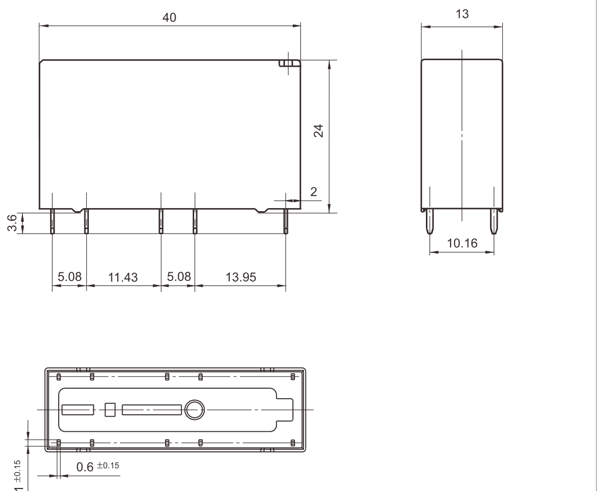 ZJA4outline — front, side & bottom views🔍 Click to enlarge
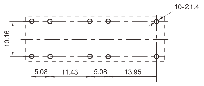 PCB layoutbottom view, 10 × Φ1.4🔍 Click to enlarge
Contact us on WhatsApp
Choose how to continue. If WhatsApp Web is unavailable, open the app or copy our number.
+8613968766559