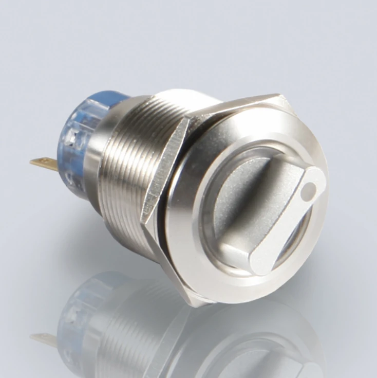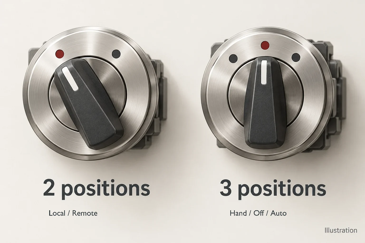
Plan the required input states before assigning selector-switch terminals. For a pump panel, Hand requests local operation, Off requests neither mode, and Auto requests automatic control. The chosen switch must provide those states in its documented contact schedule.
This guide builds a controller-input plan for a maintained Hand–Off–Auto selector. You will leave with a position/state table to use alongside the exact switch’s terminal drawing; physical terminal numbers come from that drawing. The controller and power circuit determine whether the pump may run.
1. Decide whether the task needs two modes or three.
A Local/Remote selector needs two settled positions. Hand–Off–Auto needs three because the design includes a deliberate “neither mode” setting. Three positions do not automatically mean three independent output circuits.

For our pump example, choose maintained action: the operator should be able to release the handle and leave the selected mode in place. Spring return would change that interaction, so it belongs to a different control requirement.
2. Complete the input plan before assigning terminal numbers.
Use two controller channels: HAND_REQUEST and AUTO_REQUEST. In the two-digit notation, the first digit is Hand and the second is Auto; 1 means active and 0 means inactive. Thus 10 = Hand, 00 = Off, and 01 = Auto.
| Handle position | Required contact paths | Expected controller state |
|---|---|---|
| Left: Hand | H closed; A open | HAND_REQUEST = 1 AUTO_REQUEST = 0 Local run request permitted |
| Center: Off | H open; A open | Both inputs = 0 Neither operating mode requested |
| Right: Auto | H open; A closed | HAND_REQUEST = 0 AUTO_REQUEST = 1 Automatic sequence permitted |
The table’s H and A labels name the required contact paths, not physical terminals. Center Off is a design target for this example, not a property of every three-position selector.

11 means both requests are active. In this example, the controller rejects that combination and flags a diagnostic; it is not the Off state. Handle transition states and restart behaviour separately; center Off is not a safety stop.
3. Choose an action code, then verify its contact schedule.
The J22 catalogue gives a useful shortlist. All four entries below are non-illuminated and list 2NO+2NC; the differences that affect this plan are position count and maintained versus momentary action.
| J22 model | Catalogue action | Fit with the example |
|---|---|---|
| J22-411-0 | 2-position, momentary / spring return | Does not provide three maintained settings |
| J22-411-2 | 2-position, maintained | Candidate for Local/Remote instead |
| J22-512-1 | 3-position, momentary / spring return | Action differs from the maintained requirement |
| J22-512-3 | 3-position, maintained | Position/action candidate for Hand–Off–Auto |
J22-512-3 matches the example’s position count and maintained action. Its 2NO+2NC contact count does not assign pairs to Left, Center and Right. Confirm that the exact assembly’s contact schedule provides the H/A states above before assigning terminals.
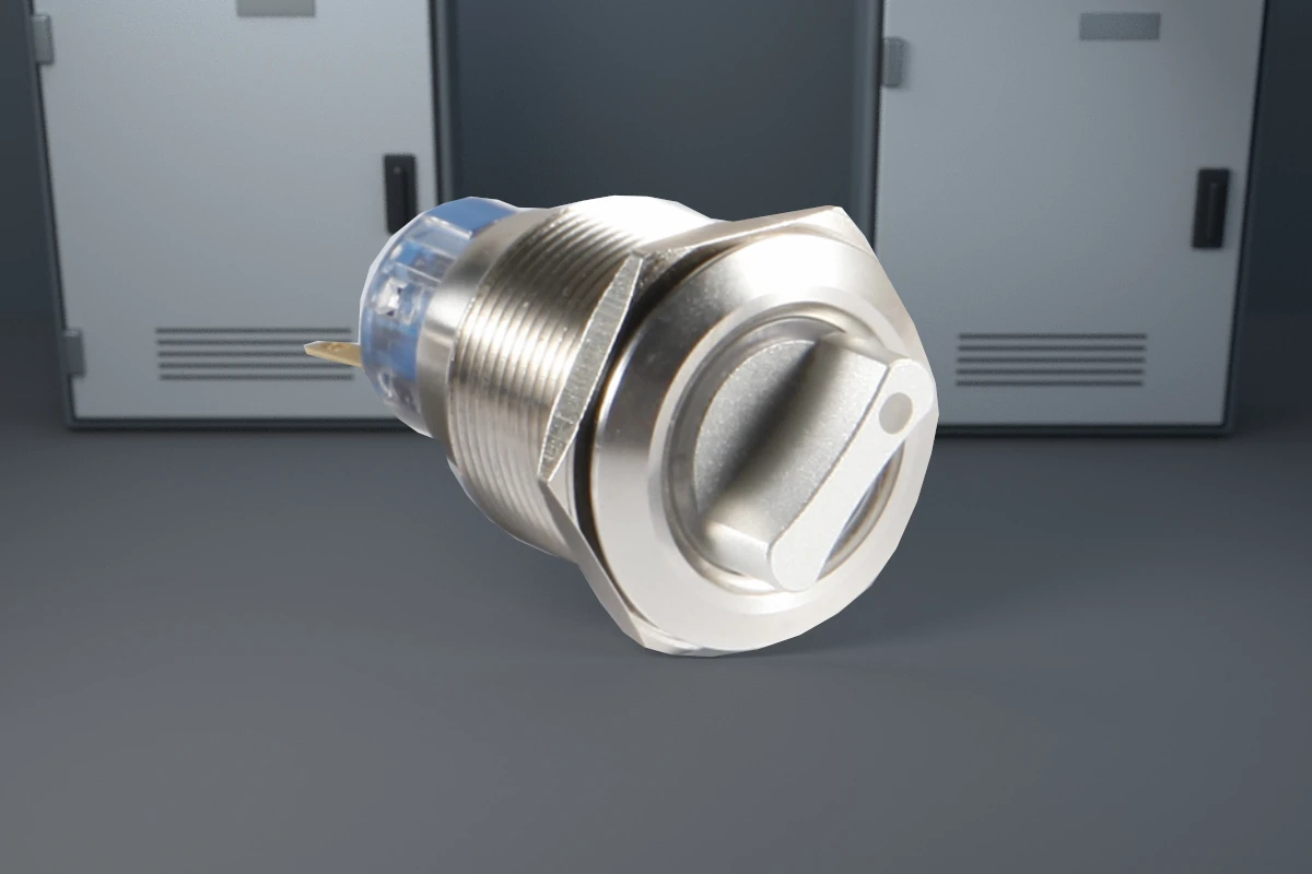
That schedule also establishes the drawing's viewing direction. “Left” viewed from behind the panel can be misleading; use actual terminal marks and the defined operator view when labeling the schematic.
4. Translate the plan into the controller's actual input circuits.
For each functional channel, enter the verified switch terminal pair, the controller's actual input channel and the documented source/common connection. Check input type, control voltage, contact AC/DC rating and minimum switching requirements against the two selected components. These determine how a closed contact becomes an active input.
The project record can now read: maintained Hand–Off–Auto; two input channels; settled states 10/00/01; 11 rejected; J22-512-3 position/action candidate. Attach the completed state table to the terminal drawing when the physical assignments are added. This gives both the wire-labeling task and commissioning a clear target.
For an isolated continuity check, a qualified person first isolates all connected sources, verifies absence of voltage and discharges stored energy under the site's procedure. Remove parallel paths that could distort readings, then measure each documented pair in all three positions and after releasing the handle. Continuity testing is for de-energized circuits and does not prove load capacity.
5. Commission against the expected states, not just the labels.
Under the controlled commissioning procedure, compare both controller input indications with the table. Hand must give only HAND_REQUEST, Off neither, and Auto only AUTO_REQUEST; every position must remain selected after release. A reversed pair of indications points back to the position mapping or channel assignment, while an unexpected center signal calls for checking the actual contact schedule.
At commissioning, compare handle position, contact state and controller input as three separate observations. A label such as “Auto” identifies the operator’s choice; the input check confirms the requested signal.
Frequently asked questions
Does maintained action preserve the operating mode after a power failure?
It preserves the handle position. The controller's restart logic determines whether returning power may resume operation or requires a new operator action.
What changes if the selector is illuminated?
Add a separate lamp circuit with its own voltage, AC/DC and any polarity requirements. Lamp illumination does not prove that the requested operating state has been reached.
Request a selector that matches the completed plan.
Explore JINHONG metal controls and selector families or the plastic control range and selector families, then open the Selector Switch category. Compare the exact model's mounting drawing for cut-out, panel thickness and rear clearance.
Ask JINHONG for a selector quotation and contact schedule. Send the state table, candidate code, quantity, required action, controller input details, control voltage, lamp needs and required approvals. Request the exact assembly's contact schedule and terminal and mounting drawings.
Continue reading
Explore the products
Compare two- and three-position maintained selector options. Both cards use the original J22 family photograph; the model names identify the position count. Request the contact schedule and terminal drawing for the exact assembly.