
Choose the LED version for the supply at the lamp terminals, including AC/DC type and permitted operating range. A machine with 230 VAC incoming power can still need a 24 VDC button lamp when its control circuit supplies the lamp.
The example below follows a Start button powered from a 24 VDC control supply. First identify your lamp circuit, then check the matching option:
| Supply at the lamp | Lamp option to select |
|---|---|
| 12 VDC | A version specified for the actual 12 VDC circuit. |
| 24 VDC | A version specified for the actual 24 VDC circuit. |
| 230 VAC | A version whose documented AC operating range and frequency cover that supply. |
Follow the lamp's supply path through the panel.
In our illustrative panel, incoming power feeds a 24 VDC control supply. The controller operates on that control circuit, and its selected status output will drive the Start-button lamp. The lamp therefore belongs to the 24 VDC circuit, regardless of the voltage printed beside the panel's mains inlet.
The nominal supply is the starting point. Supply variation and voltage drop determine the range the lamp must tolerate; the specification checklist below brings these checks together.
Read the lamp rating and contact rating as two specifications.
The lamp consumes power to produce light. The switch contacts change a separate circuit state, such as a controller input. Their rated voltage, load duty and contact arrangement do not establish the lamp supply.
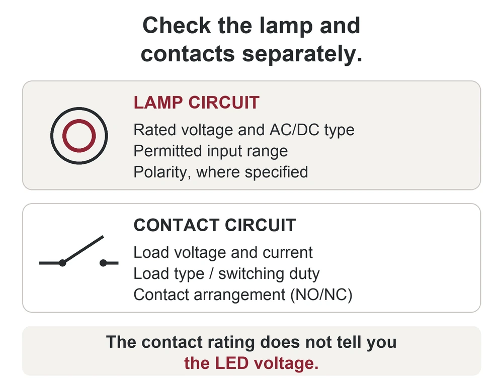
For this Start input, choose momentary action and the contact arrangement required by the controller. Select the lamp option separately: the contact-capacity or insulation-voltage field cannot identify LED voltage.
Compare voltage options using the J19 ordering information.
The J19 ordering system lists code 12 for 12 VDC and code 24 for 24 VDC. Code U220 is listed as 220 VAC; this label alone does not establish suitability for 230 VAC. For that circuit, obtain the selected lamp’s permitted AC input range and frequency, and use a documented alternative if they do not cover the supply.
The J19-271 momentary ring-button page is an action starting point for this Start input; confirm the full configuration and selected lamp data before ordering. The J19-371 latching model serves a different retained-action requirement. Compare other heads in the metal push button range.
Make the light's meaning part of the design.
Our example requires the lamp to mean “running status received,” rather than “Start was pressed.” The controller's indication logic must therefore follow the chosen status signal. Powering the lamp whenever the control supply is present would communicate a different message.
A request and a response can diverge: the operator may press Start while the controller does not accept the request. Decide which condition the light should show before assigning the output. This prevents a correctly powered lamp from giving the operator the wrong information.
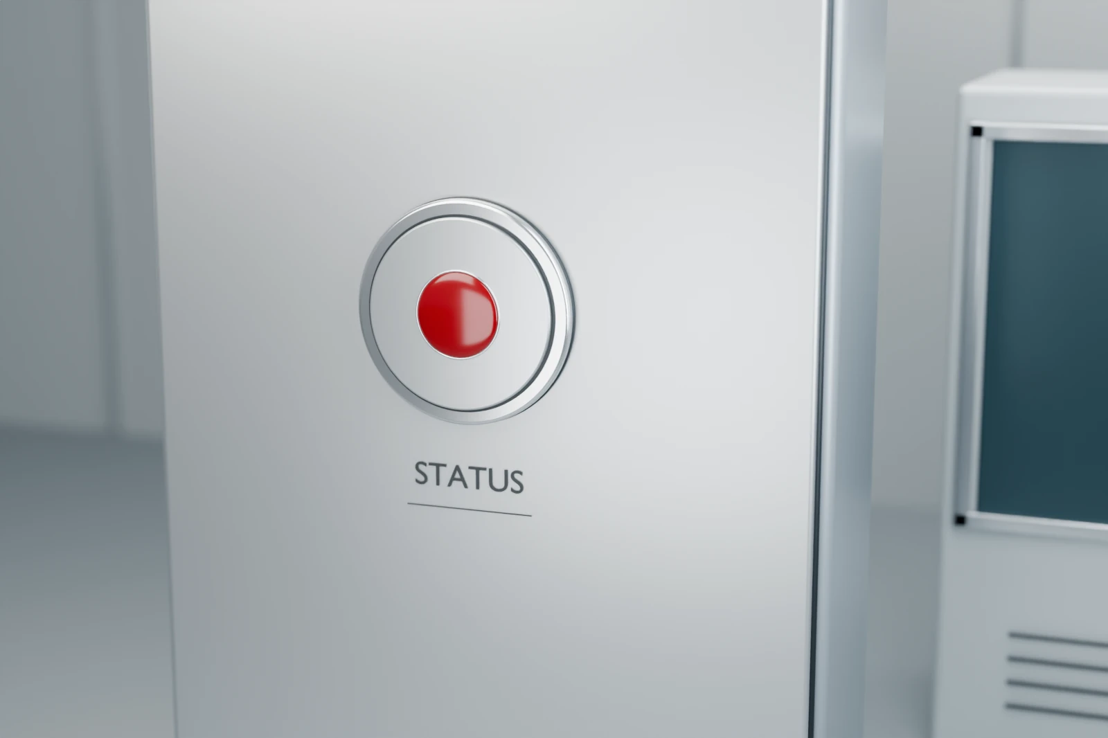
The panel label names the indication; the control logic defines when it appears. Lens colour cannot identify supply voltage or internal lamp circuitry.
Complete one selection record before ordering.
The worked result is a momentary Start button with a 24 VDC lamp driven by the running-status output. Use this record to bring the electrical, mechanical and indication requirements together:
| Selection field | Record and compare |
|---|---|
| Lamp supply | Actual nominal and minimum/maximum voltage; AC or DC; frequency for AC. The selected lamp’s operating range must cover the circuit. |
| Lamp input and output | Lamp input current, any specified polarity and switching requirements; compare these with the driving output’s capability. |
| Button and contacts | Action and reset method, required contact arrangement, circuit voltage and load duty; keep these separate from the lamp rating. |
| Fit and indication | Mounting requirements, lamp colour and the condition it represents; identify lamp and contact terminals from the selected assembly’s drawing. |
Before connection, use the selected terminal drawing and product markings with the circuit isolated. Check the assembly against the completed selection record before energising it.
Avoid three shortcuts that defeat the selection.
- Reading only the nominal voltage. Complete the operating-range and output checks in the selection record.
- Swapping a lamp because it lights during a brief trial. Brightness is not evidence of correct voltage, input current or long-term suitability.
- Modifying a finished module with an improvised series resistor. Its internal circuit and thermal design need to be known before a modification can be assessed.
Can I keep the existing colour when replacing a button?
Use the colour required by the approved operator interface. Also match lamp supply, action, contacts and mechanical fit; the same colour does not make two assemblies interchangeable.
What if the correct-voltage lamp does not light?
Check the intended status command, actual supply at the lamp and polarity against the product drawing. Then check the lamp circuit separately from the switch contacts; a working input does not prove that the illumination circuit is connected correctly.
Request the lamp data with the quotation.
Request a lamp specification, sample or quotation from JINHONG. Send the completed selection record, candidate model, quantity and required documentation so the supplier can identify the full ordering code.
Continue reading
Explore the products
Catalogue examples of illuminated push buttons. Open a model, then confirm the lamp voltage, AC/DC type and permitted input range for your ordered configuration.
